Category: 3D Printing Guide
Additional resources
Preparing for 3D printing in Rhino (McNeel Wiki page)
Lynda.com tutorials on preparing Rhino designs for 3D printing:
- Preparing a model for prototyping
- Shelling your model automatically
- Shelling your model manually
- Exporting for 3D printing
- * Note: logon to Lynda with your Bucknell account by following this link *
Simplify3D troubleshooting guide
Preform software download and user info
Make Magazine’s guide to finishing 3d prints
Cleanup your printed parts by removing support, sanding, and/or gluing
Included below are images of some of the most common tools you’ll use in the finishing process.
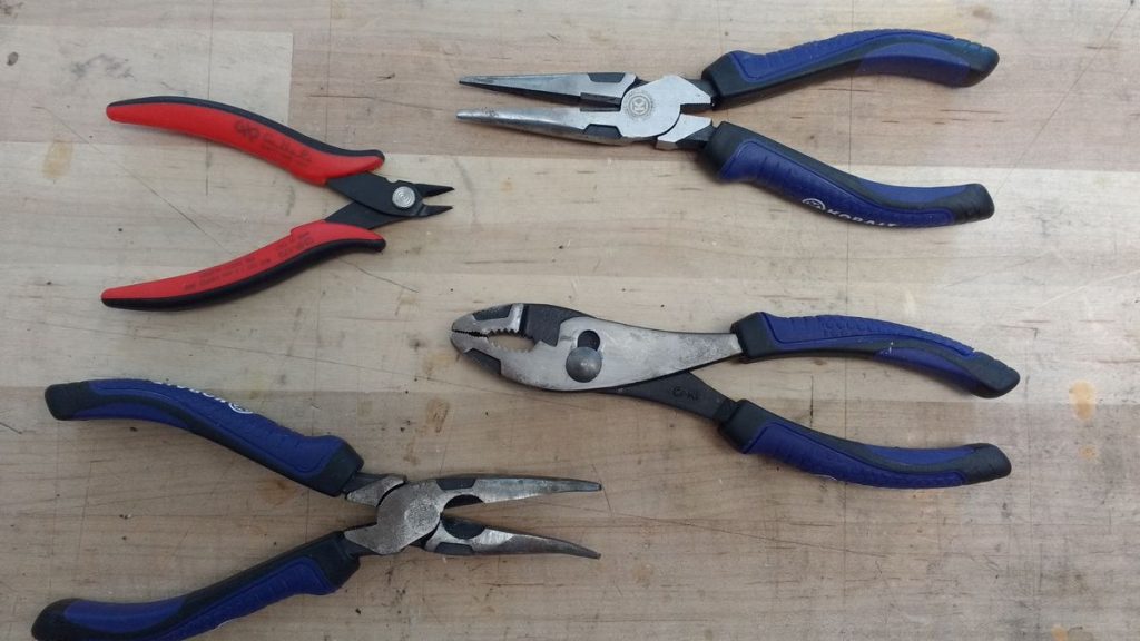
Pliers (blue handles) and snippers (red handles). Great for ripping support material off and snipping it away.
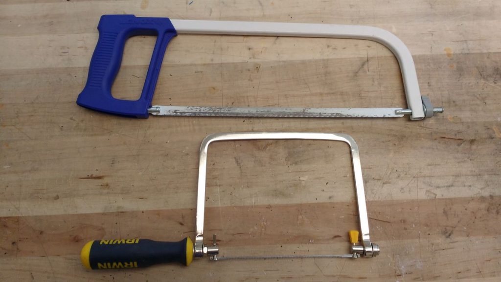
Hacksaw (top) and coping saw (bottom). Use for making big alterations to a printed part.
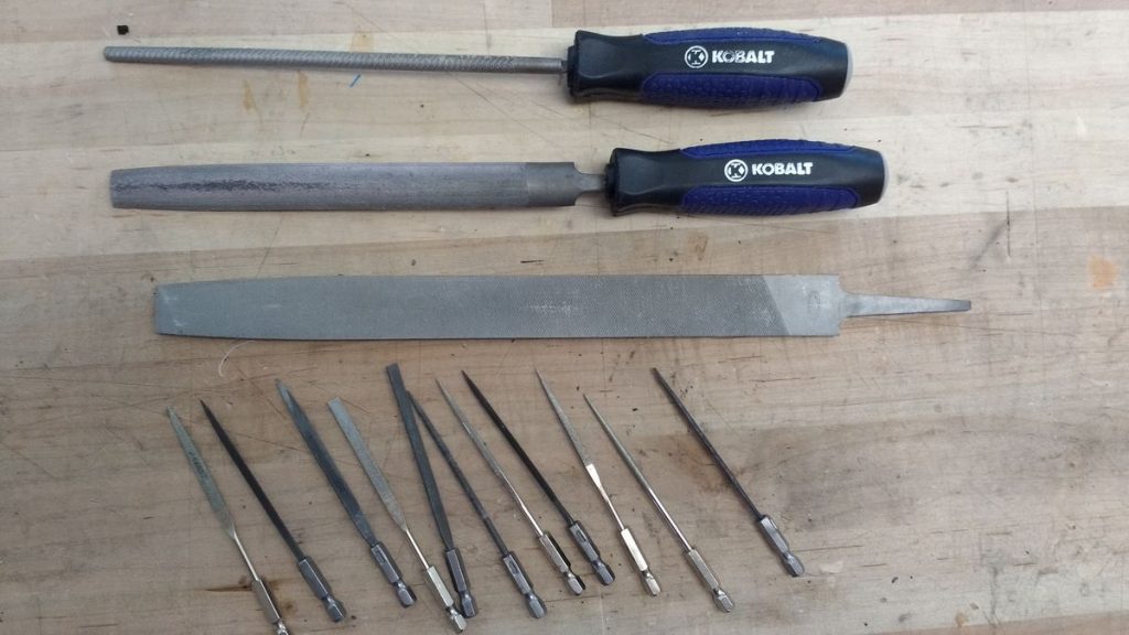
Files. Good for smoothing the surface of a print after removing support. Choose the shape and size that’s best suited for your part(s). The MakerSpace has standard files for general use, and needle files for detailed work.
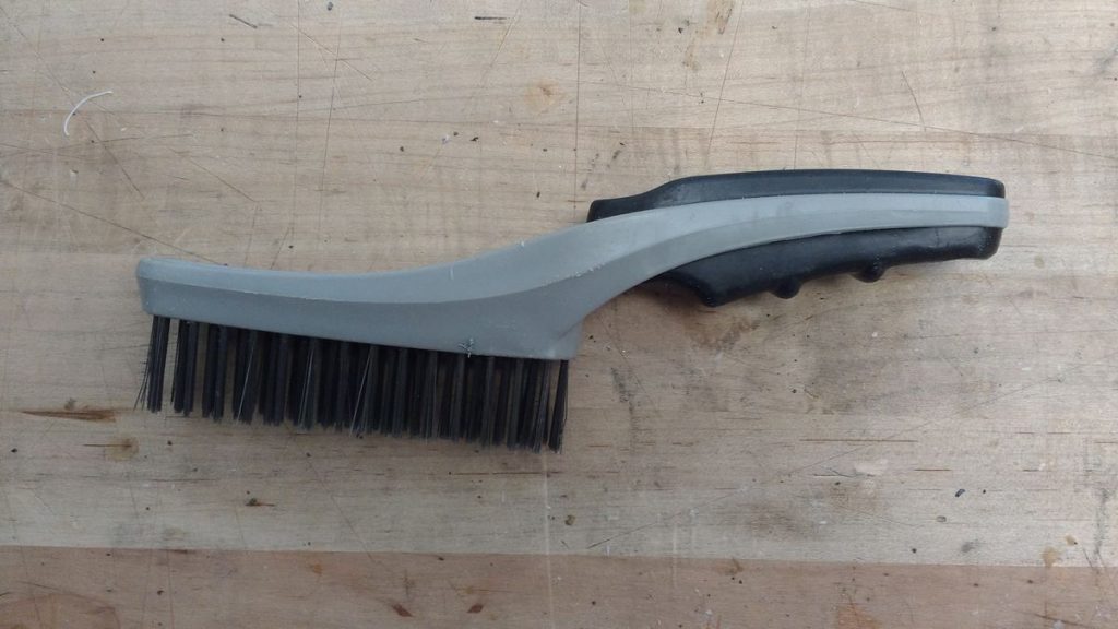
Wire brush. The files sometimes get clogged up. Use the wire brush to clean the files.
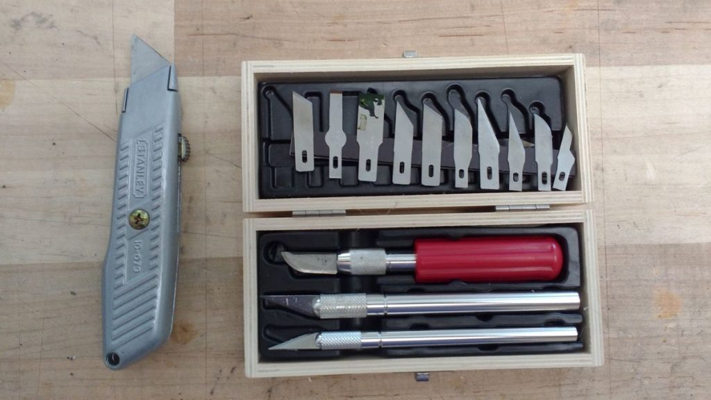
Razors. The box cutter and xacto knives are useful for precise shaping. Please, for the love of all that is good in the world, always cut AWAY from your hand so that when you slip you’ll slice through air and not flesh.
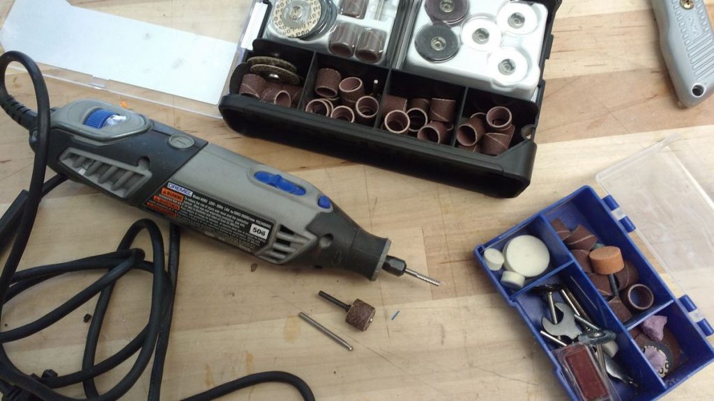
Dremel. The dremel has a variety of abrasive bits for smoothing, shaping, and cutting. Use with safety glasses.
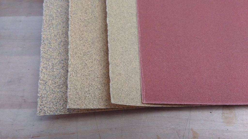
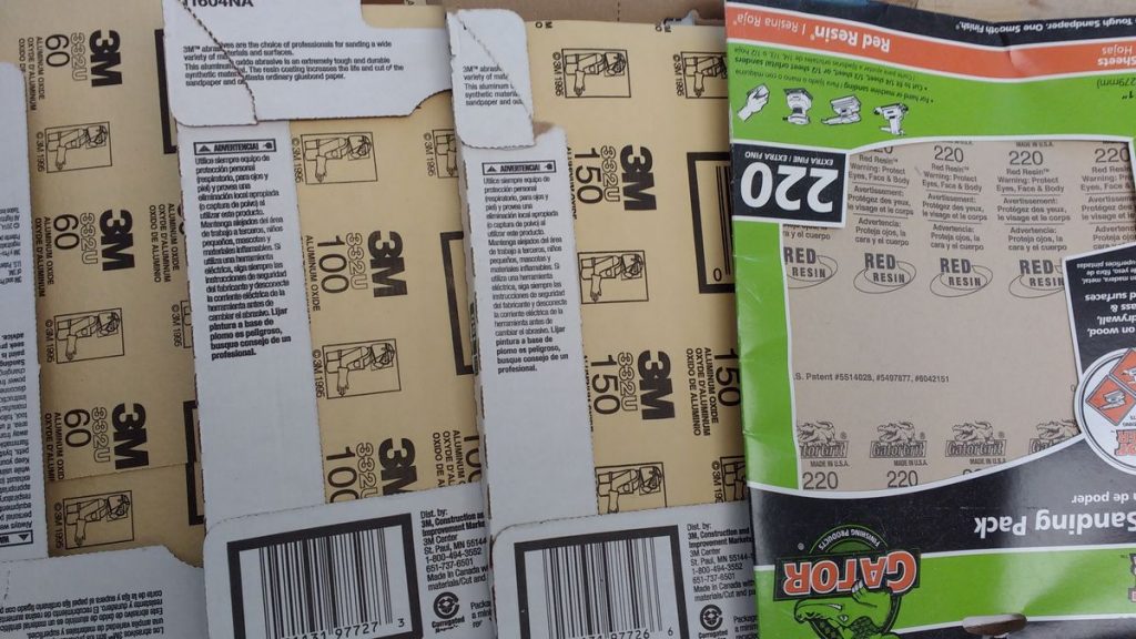
Sandpaper. Use coarse grits like 60 and 100 grit for rough shaping, and fine grits like 150 and 220 for smoothing. The grit is specified on the back of the sheet.
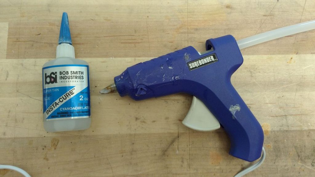
Glue. Superglue (left) is great for tight fitting parts, but it won’t fill gaps. Hot glue (right) is better for big gap-filling glue jobs. Please use caution with superglue and don’t get it on your skin or in your eyes!
Follow best practices for 3D printing
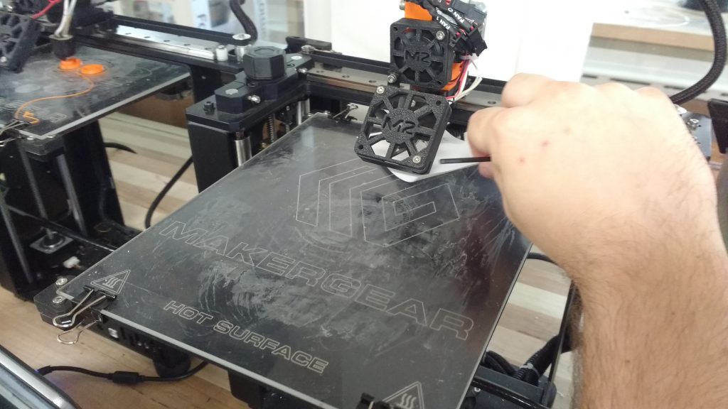
Level the print bed before every job. For best results with the MakerGear and MakerBot printers, level the bed before every job. This will help the filament adhere properly to the bed and distribute evenly. In the image below we see a Student Technician using a sheet of paper to set the correct amount of space between the hotend and print bed.
Note that the leveling procedure is only to be performed by a trained Student Technician because the printer can get damaged if the process is done incorrectly. Ask the Student Technician on duty to help you.
Make sure there’s enough filament on the spool. With small prints and a full spool it’s easy to know that there’s enough filament left, but if you’re printing a larger job you may need to weigh the filament spool to be sure. When you were setting up the toolpath in Simplify 3d, if you made a note of the plastic weight required for your part you can figure out if there’s enough filament on the spool. Here’s how:
- Find a completely full roll of the same filament brand and type (e.g.: Hatchbox ABS) and weigh it.
- Look at the side of the full roll and find the weight of the filament. (usually 1kg)
- Subtract weight 2 from weight 1. This is the weight of the empty spool.
- Now weigh the spool (with filament) from the printer you want to use, and subtract the weight of the spool. This is the weight of the filament left on the spool.
Clean the build plate and add glue before every job. Scrape the build plate with a putty knife to eliminate glue bumps from previous print jobs. Add a fresh coat of glue stick to the build plate to help the first layer of ABS stick during your print job.
Watch the print closely for the first half hour. The first few layers of the print are like the foundation of a house. A bad foundation can cause all sorts of problems with the walls and roof. Watching closely for the first half hour will give you a chance to catch problems early and restart the job if needed.
Is the print bed level? Do the outer walls of the print look like they should? Is the support material building up okay? Are the parts adhering to the build plate? Curling up along the edges (as shown below) can cause a part to deform considerably or fail altogether.
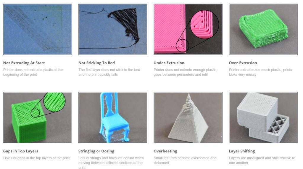
Troubleshoot. Simplify3D has created an excellent troubleshooting guide for 3D printing that you can refer to when you encounter problems. Here’s a link.
Create the toolpath for your 3D print
Toolpaths
To 3d print a form we have to create what’s called a toolpath. A toolpath consists of numerical g-code, which is essentially a set of instructions that tells the 3d printer what to do. Fortunately, we don’t have to learn to write g-code because the software writes it for us based on how we arrange things in the graphical interface and the settings we enter. There are two main programs you’ll use for 3d printing in the Makerspace: Simplify3d (for the Makergear and Taz printers), and Preform (for the Formlabs printer). The 3D printing tutorials on the MakerSpace website cover everything you need to know about Preform, and almost everything you need to know about Simplify3d, but let’s go over a few more points that you’ll find helpful when using Simplify3d and the MakerGear printers.
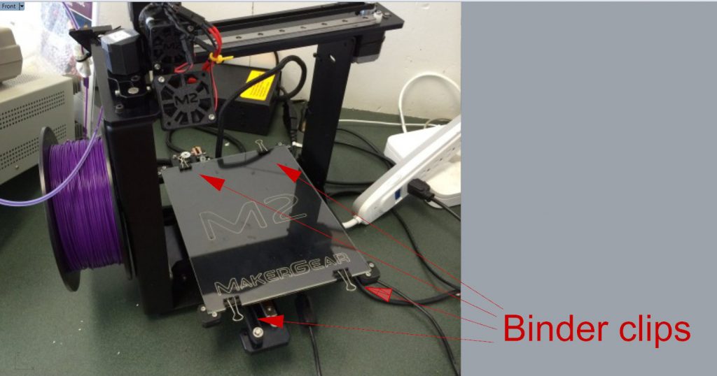
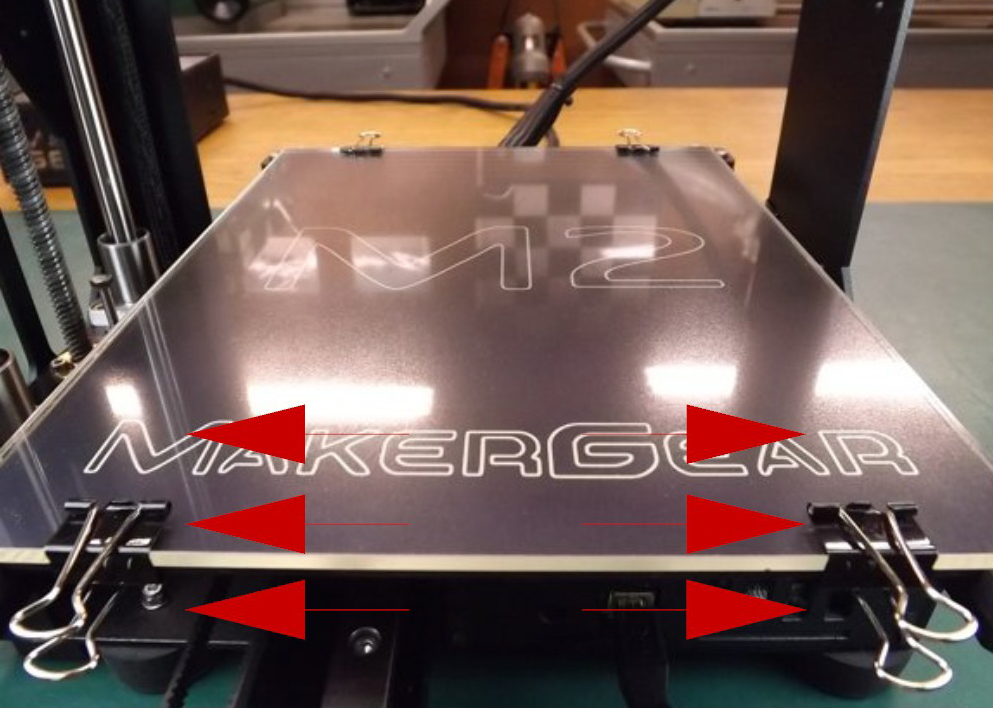
Don’t hit the binder clips! When working with Simplify3D in preparation for printing on a MakerGear, remember that there will be binder clips holding down the print bed. (see below)
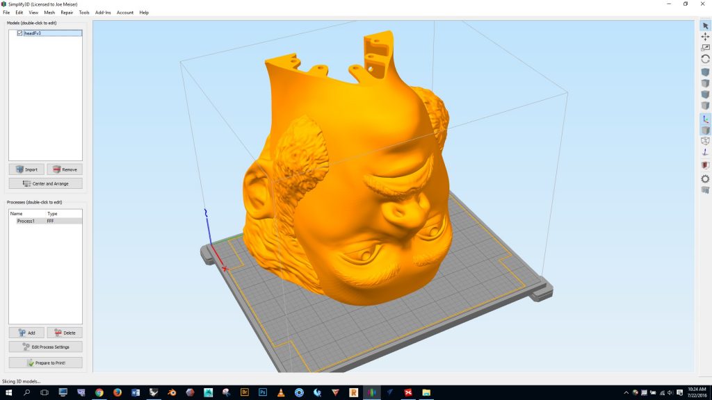
If your toolpath runs the printer’s hotend into the binder clips it will mess up the print job and it may damage the printer. With this in mind, I have created a simple boundary mesh (see below) that I load in with each Simplify3D print job. This boundary mesh constrains the travel movement of the hotend and ensures that it won’t hit the binder clips. If you’d like to use this mesh, here it is as an STL file, and here it is as a Rhino file. I admit that my boundary mesh could probably be scaled down a bit– if you make improvements to it please share them with me and I’ll update these files.
Move the binder clips as far to the left and right as possible. When the print job starts the binder clips will be dreadfully close to some bolts at the top of the machine. Putting the clips to the far left and right will keep the clips from running into the bolts.
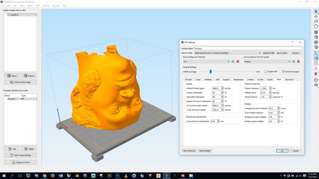
Lower the movement speed when printing large or tall parts. When printing a large part using the printer’s highest movement speed, the printer may get out of alignment in the Y axis. This is because large parts have significant mass, and as the bed jerks back and forth the inertia can cause the printer to exceed its intended path. Tall parts, on the other hand, are susceptible to detaching from the print bed when the bed movement is jerky. If you look in the “other” panel of the process settings you’ll see the box where you can adjust the x/y axis movement speed. By default the movement speed will be set to 18,000 mm/min. I have found 9,000 to work to work well with large and tall part on the Makergear printers.
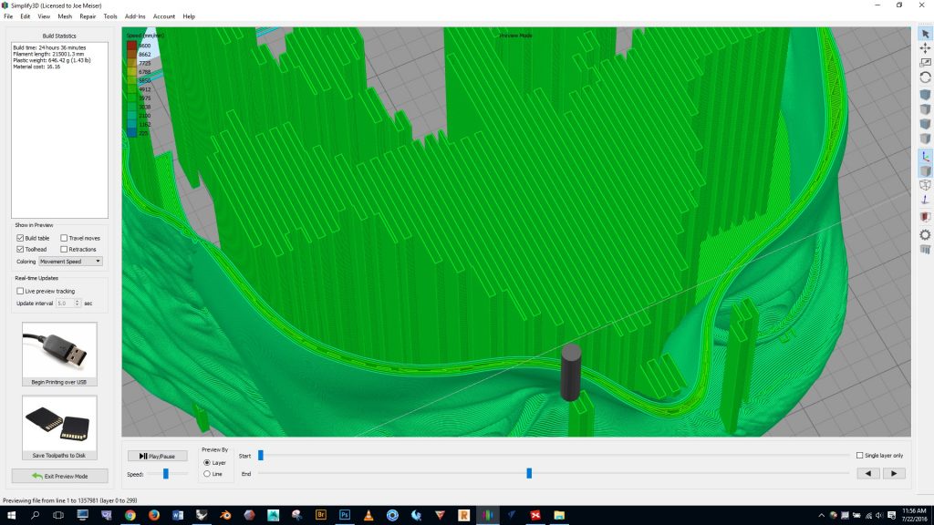
Carefully inspect the toolpath before printing. After you’ve entered all of your settings and you’ve clicked the “prepare to print” button, take a few minutes to examine the toolpath. This can save you from running a failed or substandard print job, so it is worth the time.
While looking at the print preview, ask yourself:
- Is there enough support in areas that need it?
- Is the resolution of the print sufficient?
- Are there any holes in the model from boolean processes gone wrong?
- Check the travel moves — does it look like the hotend will run into the binder clips?
- Examine the lowest layer — does it look like the print will make consistent contact with the printer bed?
- What will it be like to remove the support material and cleanup the print? Is the support material going to obscure areas of high detail that will be hard to cleanup? If so, should you make adjustments to the print setup to make the cleanup process easier?
- Is the build time acceptable? The longer a job runs, the more likely it is to fail. Also, keep in mind that Simplify3d tends to underestimate the time required. Add 25% to get a realistic estimate. If you’re dealing with multiple parts it may be better to run a few separate small jobs than one big job.
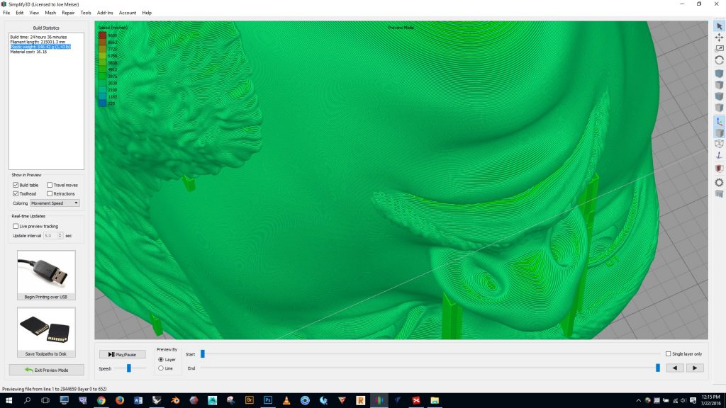
Make a note of the plastic weight. Knowing the plastic weight (highlighted in blue below) will enable you to accurately gauge whether there is enough filament on the spool to complete your job.
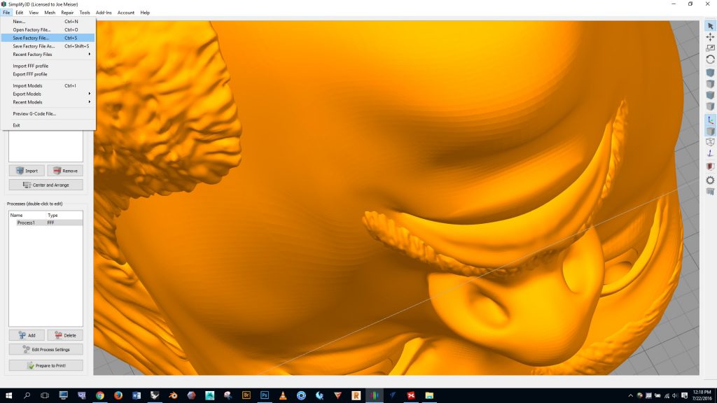
Save the factory file. The factory file includes the geometry of your project and all of the process settings you’ve created. It’s helpful to have this file in case your job fails and you need to make an adjustment prior to reprinting.
Export the mesh from Rhino in STL or OBJ format
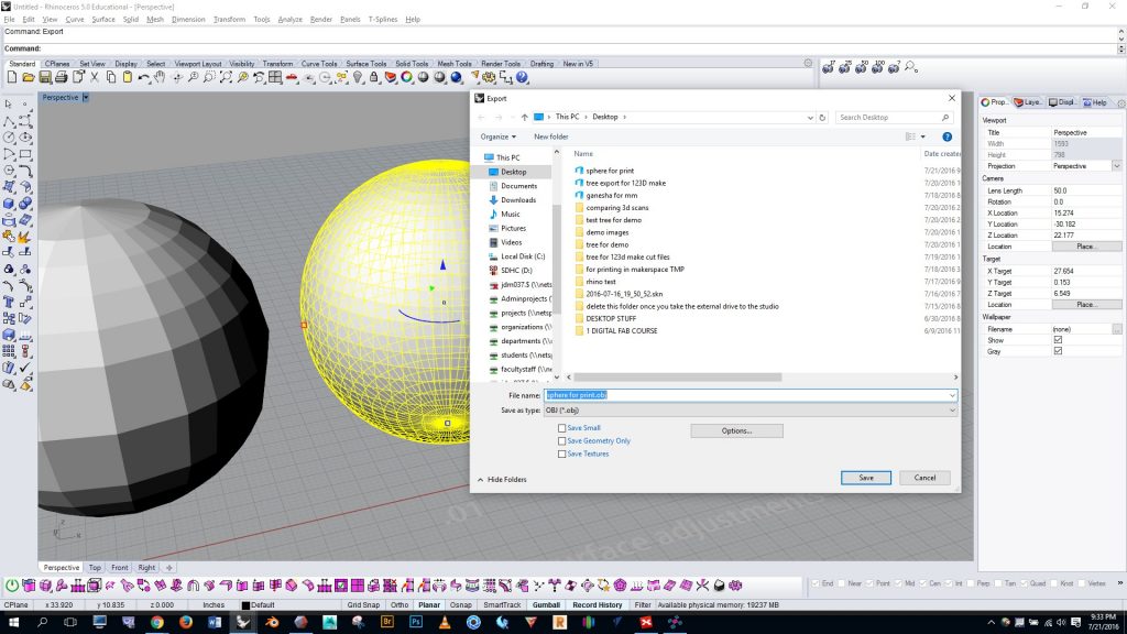
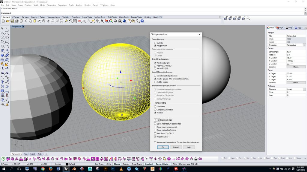
Fortunately, exporting the file is simple. Select everything you want to export, and then run the “export” command. Choose to export your file as an OBJ or STL.
The only difference I know of between these file types is that OBJ files can contain texture information while STL files are strictly for geometry. If you intend to order a full color sandstone print from Shapeways, for example, (see below) you would need to send texture information along with the geometry so you’d want to use OBJ format.
These are the settings I typically use for exporting meshes:
Check the mesh for errors, then repair as needed
Even if your NURBS form is a single watertight solid there’s still a chance it will produce a mesh with errors. Errors in the mesh can cause problems during the printing process. Let’s look at how to check for errors and how to repair them.
Mesh repair in Rhino
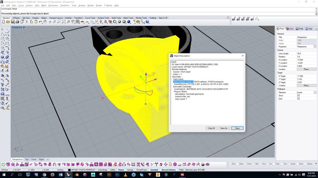
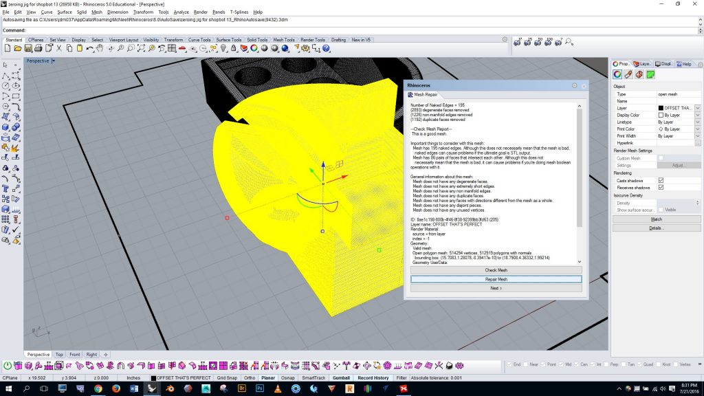
In the example below the original NURBS polysurface was a closed solid, but by running the “what” command we see that it produced an open polygon mesh.
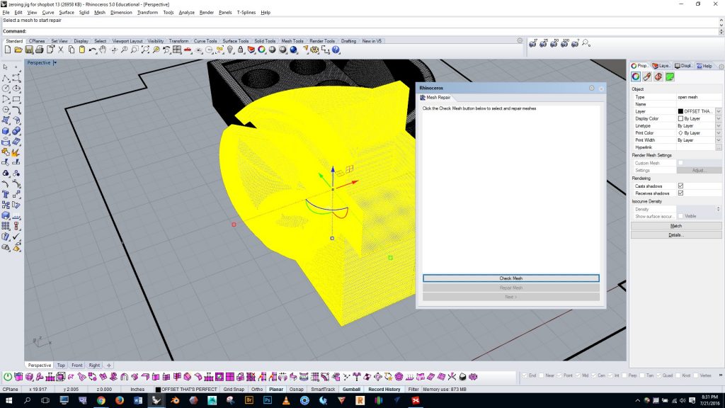
Let’s run the “meshrepair” command (shown below) and click the “check mesh” button at the bottom.
We see that we have a bad mesh with degenerate faces, non-manifold edges, and lots of duplicate faces. Let’s click the “repair mesh” button.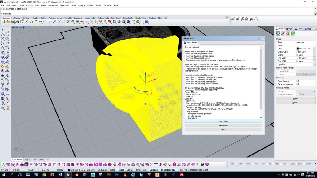
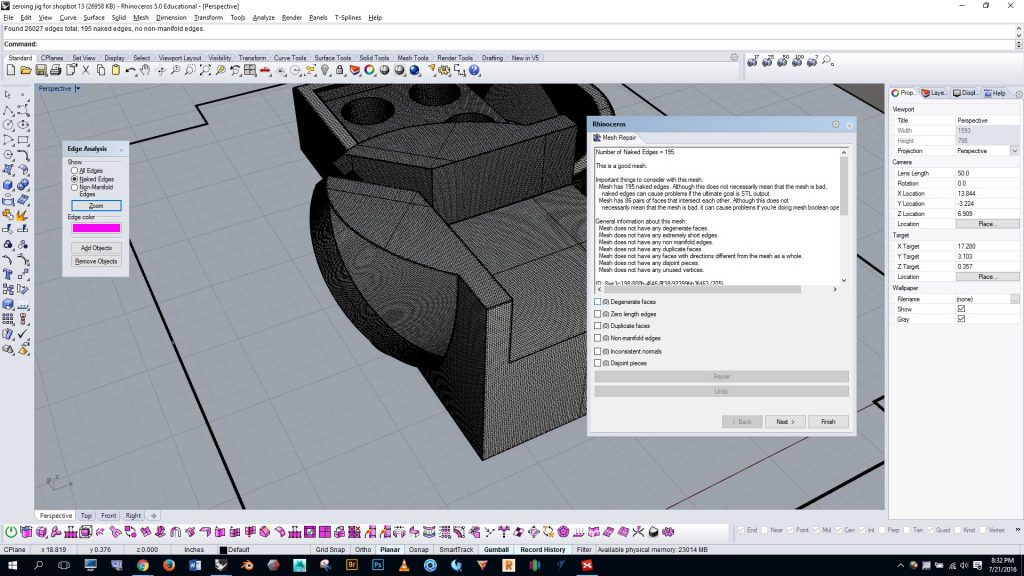
And we see that the degenerate faces, non-manifold faces, and duplicate faces are removed. But looking further down the list we can see that there are still many naked edges. Let’s click on the next button…
If there were remaining issues with degenerate faces, etc. we would have the opportunity to fix them on this screen. Sometimes when we fix one problem it creates other problems, so you may have to run the repair several times in a row on different problems to resolve everything. Now let’s fix the naked edges…
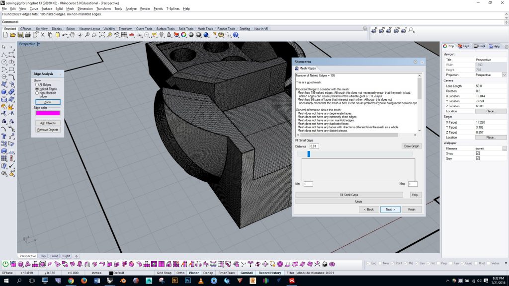
Naked edges on a mesh are often due to small gaps. By adjusting the value in the distance box and clicking the “fill small gaps” button we may be able to close the naked edges.
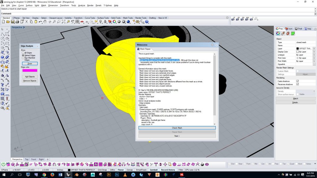
We see that the naked edges have been fixed and we now have a good mesh, but the part still has “86 pairs of faces that intersect each other”. At this point, since we now have a good mesh, we could go ahead and export the mesh and create the printing toolpath. It would be wise, however, to carefully inspect the toolpath in case the intersecting faces cause any problems. We’ll look at toolpath inspection on the next page.
Mesh repair in netfabb
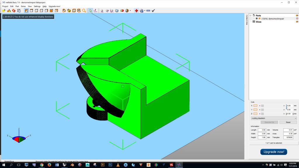
For the sake of demonstration let’s look at another program that can help resolve mesh errors. Let’s export the part as an STL and open netfabb basic — this is a free program that you can download from here.
Open netfabb and go to “project”, “add part”, and select your part. Once your part opens click on your part to turn it green and then click the red plus button at the top of the screen, as shown below.
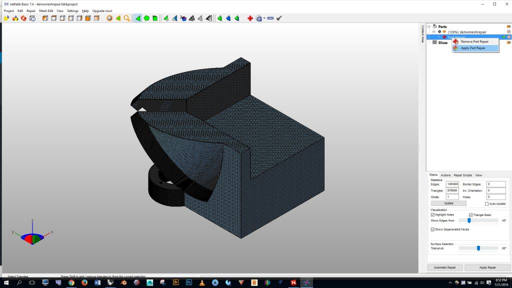
Now look over at the top right of the screen. Right click on “part repair”, click on “apply part repair”, and then choose to remove the old part.
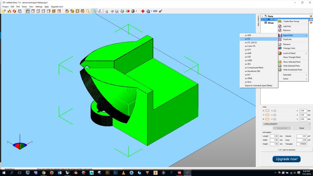
Finally, again in the top right, right click on your part in the part list, select “export part”, and export as an STL file. Choose to optimize the part, and then export it. The errors should be repaired– check the part in Rhino to be sure.
Make solid in MeshMixer
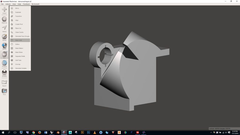
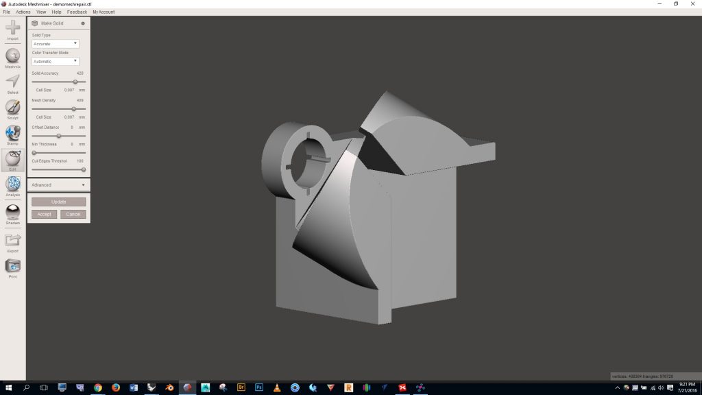
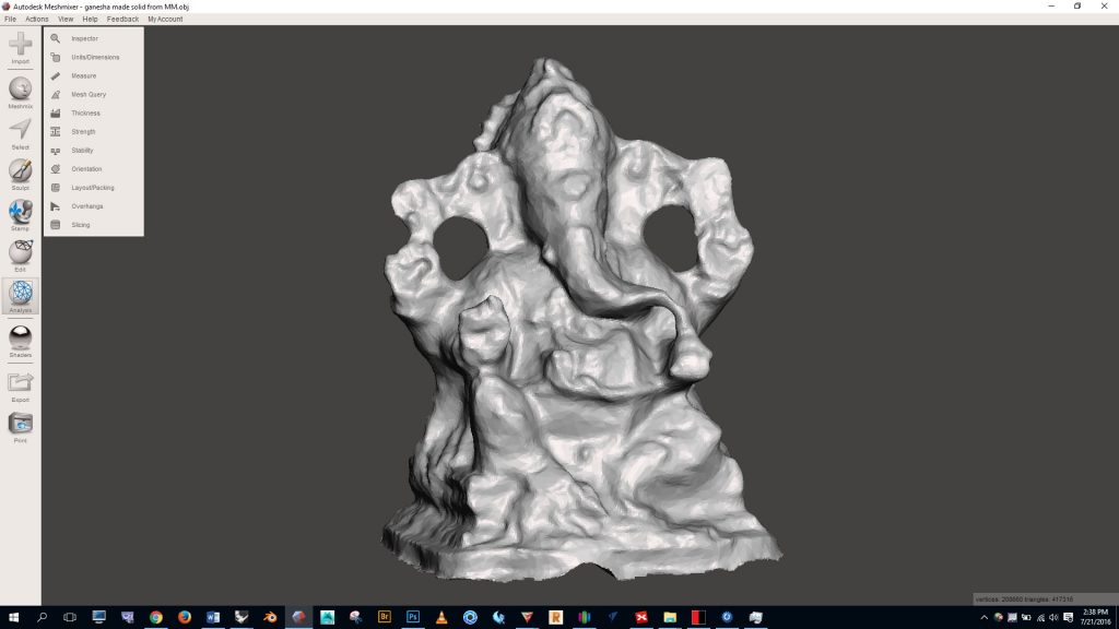
Meshmixer can also be used to fix mesh errors. Meshmixer’s make solid function may reduce the density of your mesh, so proceed cautiously. Once you open Mixermixer and import your file, click on “edit” (on the left), then “make solid”, as shown below.
By the way, notice below that Meshmixer rotated my part on import. You can keep this from happening by clicking on “file” > “preferences” > “file” > and then check the “flip Z-Y axis on import export” box
When running the make solid command I usually use the “accurate” solid type, and I set the “solid accuracy” and “mesh density” sliders up pretty high to preserve mesh density. You can tinker with the settings and click “update” to see what the result will be. When you’re happy with the settings click “accept”. This process will probably resolve the mesh errors — take the form back into Rhino to check.
[return to 3D Printing Guide main page]
Turn your NURBS model into a mesh of appropriate density
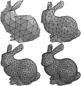
In Rhino we model with NURBS, which is a mathematical representation of form. 3D printing programs, on the other hand, work with STL and/or OBJ files, which are both mesh formats. We therefore need to convert the NURBS form to a mesh in preparation for 3D printing. It’s possible to directly export a NURBS form from Rhino as an OBJ or STL, but if you do this you won’t have a chance to inspect the mesh. It’s important to inspect the mesh because it may not capture sufficient detail, or it may be more dense than necessary. If your mesh lacks sufficient density you’ll get a faceted looking 3D print, and if the mesh is too dense you may crash the 3D printing program. With this in mind, it’s best to convert your NURBS form to a mesh, inspect it carefully, and then export.
Meshing a NURBS form
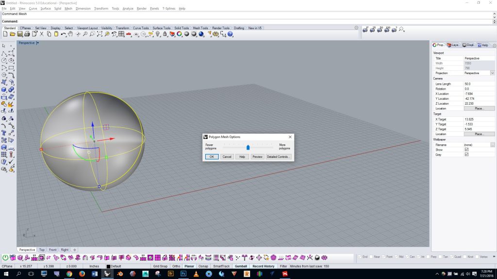
In Rhino, select your NURBS polysurface and run the “mesh” command. By default you’ll see the simple slider, as shown in the image below. For some projects you may get decent results by adjusting this single slider. However, the simple slider sometimes doesn’t give enough control. So if you click on the “detailed controls” button that’s below the slider you’ll be given more options…
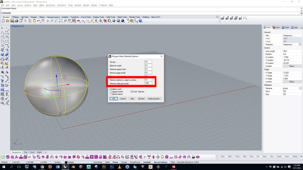
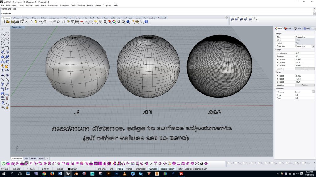
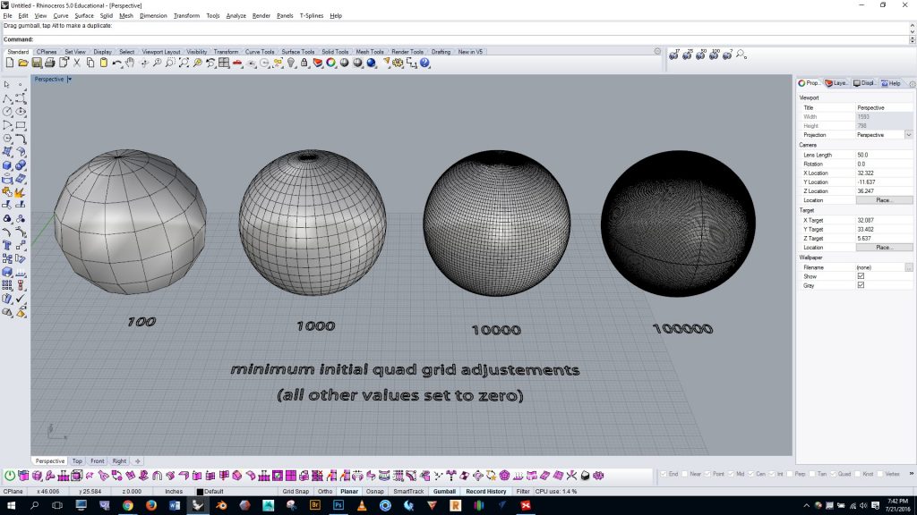
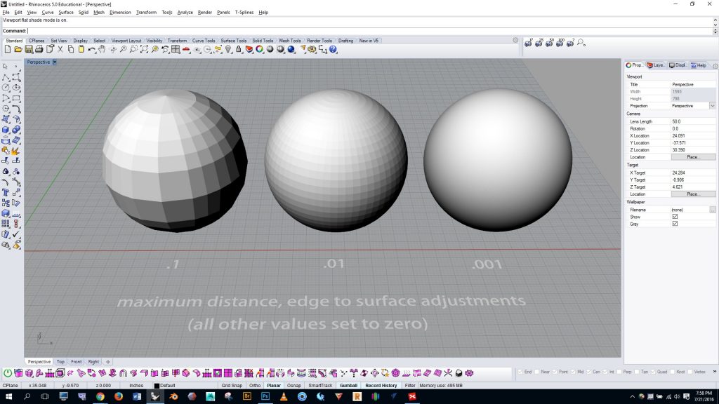
Start off by entering zero in all of the boxes, and then turn your attention to “maximum distance, edge to surface” and “minimum initial quad grids”, marked in red below. These settings have the greatest effect. You can increase the density of the mesh by lowering the value of “maximum distance, edge to surface”, or by raising the value of “minimum initial quad grids”. Some comparison meshes and settings are shown below…
Inspecting the mesh visually
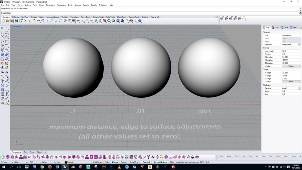
You can get a good sense of the quality of the mesh by visually inspecting it. However, shaded view (as shown in the image above) and regular rendered view (as shown below) don’t enable us to accurately see what the form will look like after it is printed…
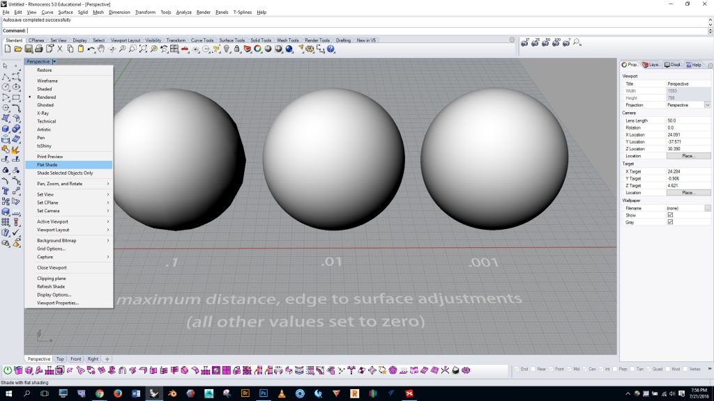
As shown below, with rendered viewing mode on, click on the dropdown arrow in the top left of the viewport, and then turn “flat shade” on.
Notice in the image below how the facets on the spheres become much easier to see.
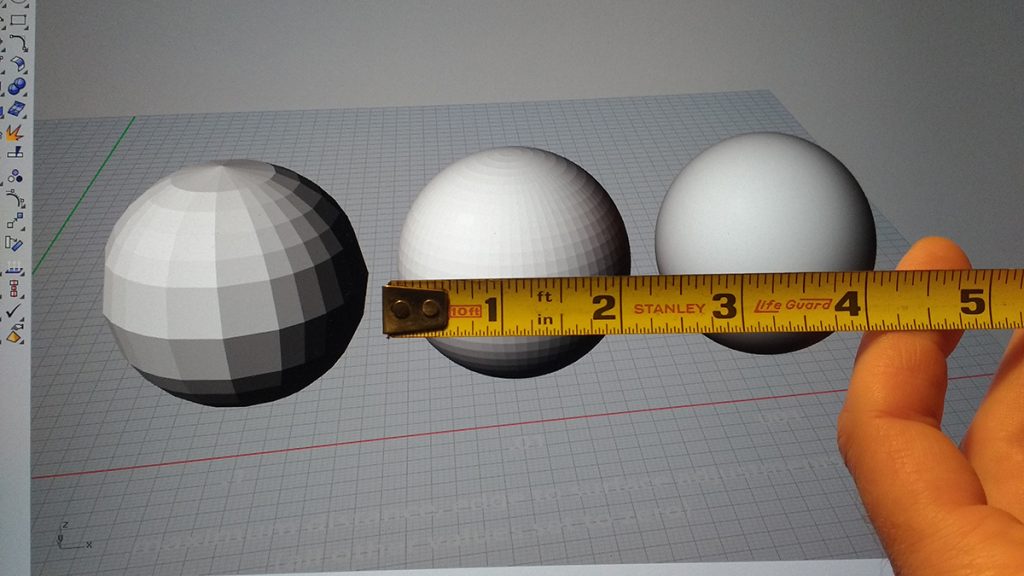
Now, to get a sense of how the mesh will look when printed we need to see the sphere at its actual scale. Get a tape measure or ruler and hold it over the monitor and then scale your object to match the size you intend for the print. In this case I’m assuming that I’ll print the sphere at 2″, and you can see that at this scale the mesh is visible. This tells me that I probably want to create a mesh of greater density than the center sphere.
Inspecting the number of verteces.
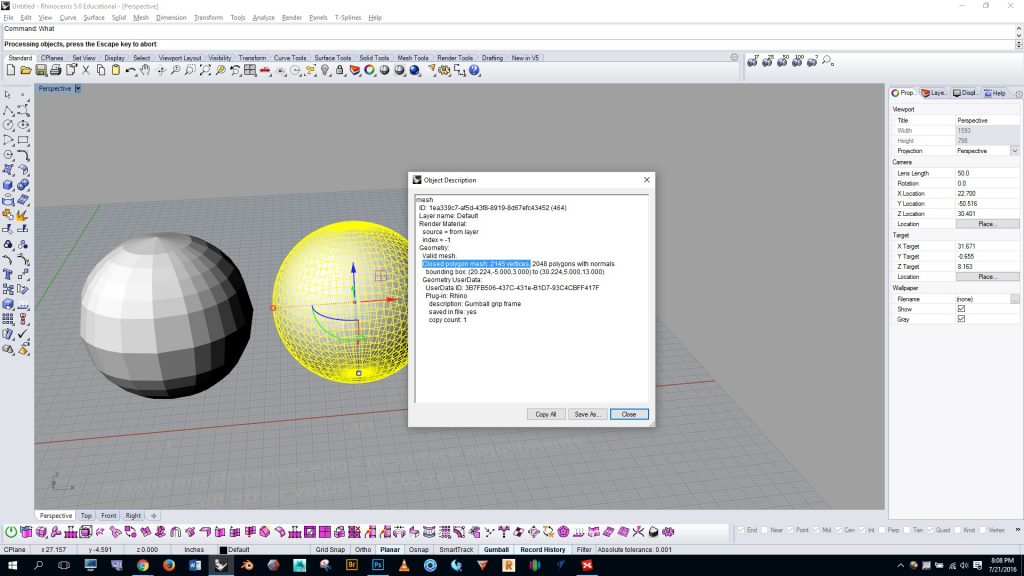
We can also inspect the mesh with the “what” command. As you can see below, the center mesh has 2,145 vertices (mesh points). This is, of course, well within the acceptable limit. However, I ran a print job in the MakerSpace the other day with a collection of parts that had 2,032,909 vertices in total, and Simplify3D ran verrrry slowly. This was probably due in part to the old processor on the MakerSpace laptop, but still, the experience gave a sense of the limitations we face. If you exceed 2,032,909 vertices you may crash the computer.
Modify to facilitate an easier printing process / achieve a desired result
Many modifications can be done in Simplify3D and Preform, but I find it easier and faster to modify in Rhino. In Rhino we also have more control for certain operations, we have a more complete set of tools, and we’re able to use the orthographic viewports. Here are some modifications you may want to make as you prepare to 3D print your part:
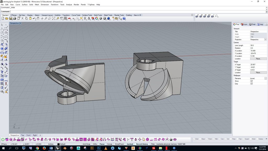
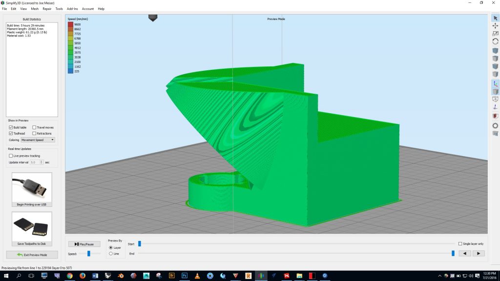
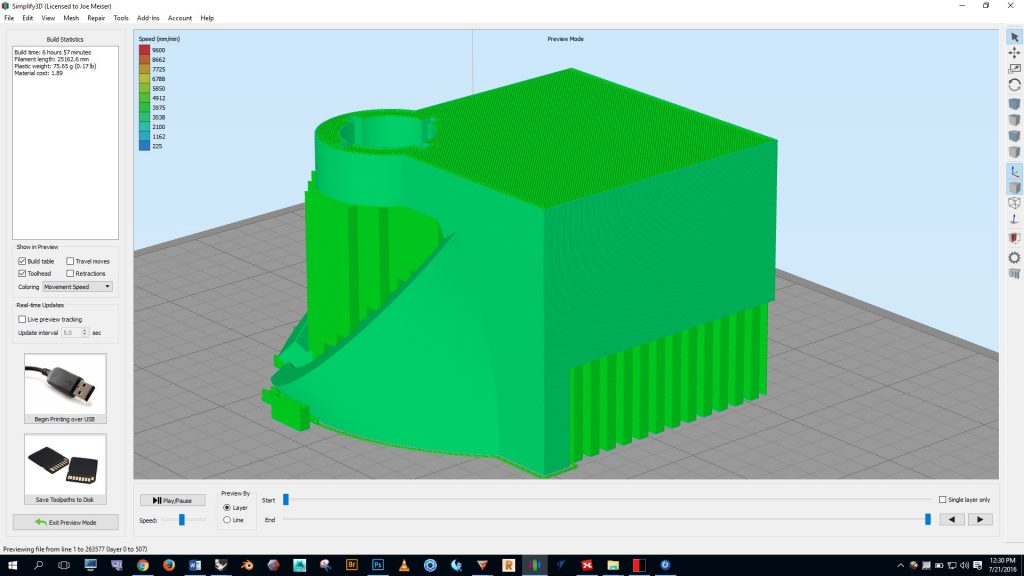
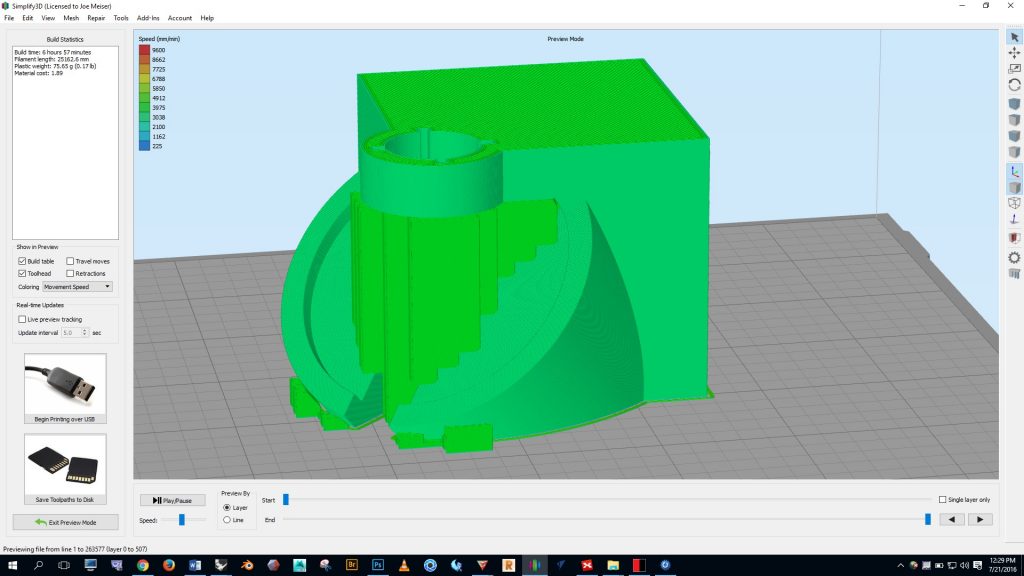
Orient parts to reduce the amount of support needed and control the placement of the support. By rotating parts in XYZ we can reduce the amount of support needed (which will speed up the print job), and we can keep support off of detailed areas (which will make post-print cleanup easier). Take a look at the example below. Here we see the same part in two different orientations. The FDM (aka FFF) printers in the MakerSpace can print a 45 degree overhang without support, so the orientation on the left can be printed without any support. See the screenshots below from Simplify3D to see how the orientation on the left would not require support, while the option on the right would require support.
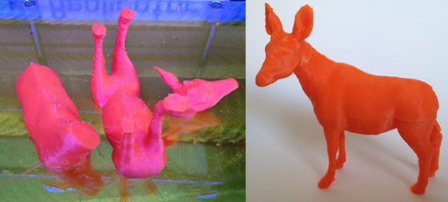
Orient parts for best resolution. Models can be sliced into pieces if necessary and then re-assembled. On Fused-Filament Fabrication printers, you can only control the Z resolution. The X and Y resolutions are determined by thread width. If your model has fine features, make sure the model orientation is cable of printing those features.
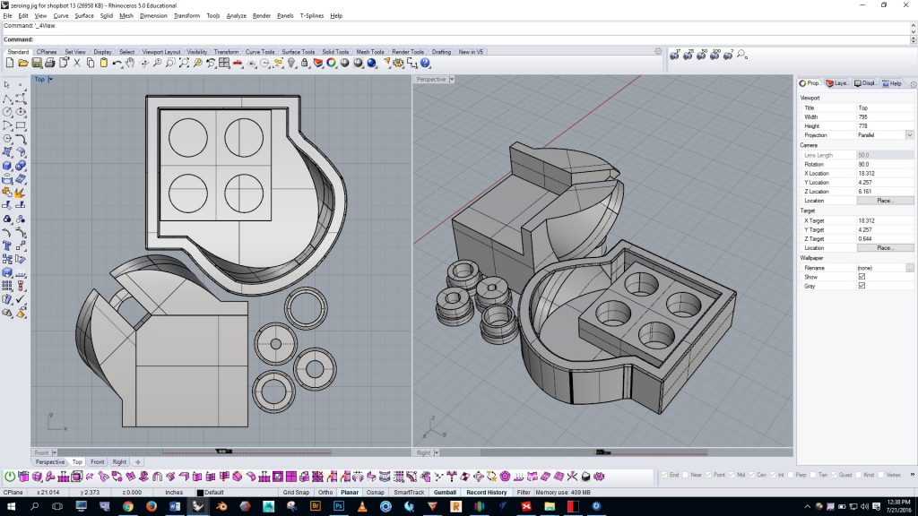
Arrange parts close together. Moving parts close together will decrease print time by reducing travel. Use the top viewport in Rhino scoot parts close together. An effective arrangement is shown below.
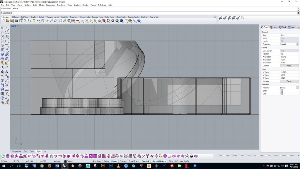
Ensure contact with ground plane. If you plan to export multiple parts from Rhino together for printing you’ll need to make sure that the bottom of each part meets the same ground plane. Use the front and side viewport to ensure that all of the parts meet the ground plane (see below). Zoom in very close to inspect.
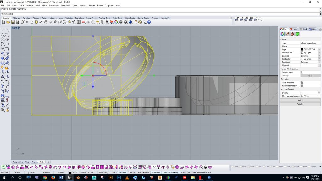
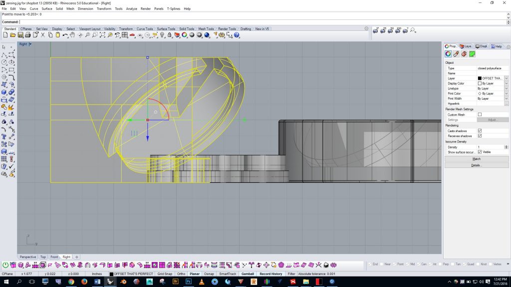
If you think a part might be too high or too low, use the move command and your osnaps to relocate it. Below you can see an example of moving the highlighted part from its bottom left corner to the bottom quadrant of one of the cylinders. Once this action is complete we can be certain that the two parts are aligned with the same ground plane.
In the example below the highlighted part makes contact with the ground plane only at a single point. In this case the part needs to be rotated with the vertex osnap and ortho along both the x and y axes.
Split the model and use offset pins for registration
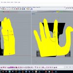
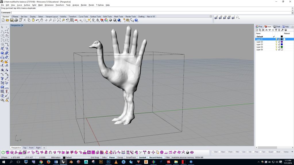
I wanted to print the project below to be 11″ tall, but the work envelope on my MakerGear printer is only 8″ x 10″ x 8″ (XYZ). I’ve drawn in the MakerGear’s work envelope in the example below.
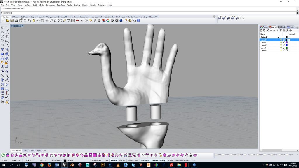
I decided to cut the form in half and print it in two parts. Obviously, this makes things a bit more difficult because then the two parts have to be assembled after it’s printed, but with registration pins the assembly becomes easier.
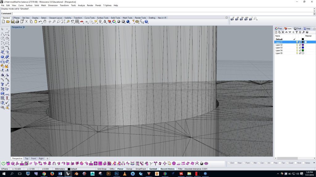
If the pins are exactly the same size as the hole they won’t fit in, so we need to make the pins slightly smaller as shown in the image below.
Getting the tolerances correct for interlocking parts can be difficult. Some tips: use a 0.2mm offset for a tight fit and a 0.4mm offset for loose fit {{ that is .0079″ and .016″ respectively }}. You will have to test it yourself with your particular model and the printer you’re using to determine what is the right tolerance for your situation. I found that a .4mm offset worked well for the ostrich hand pins.
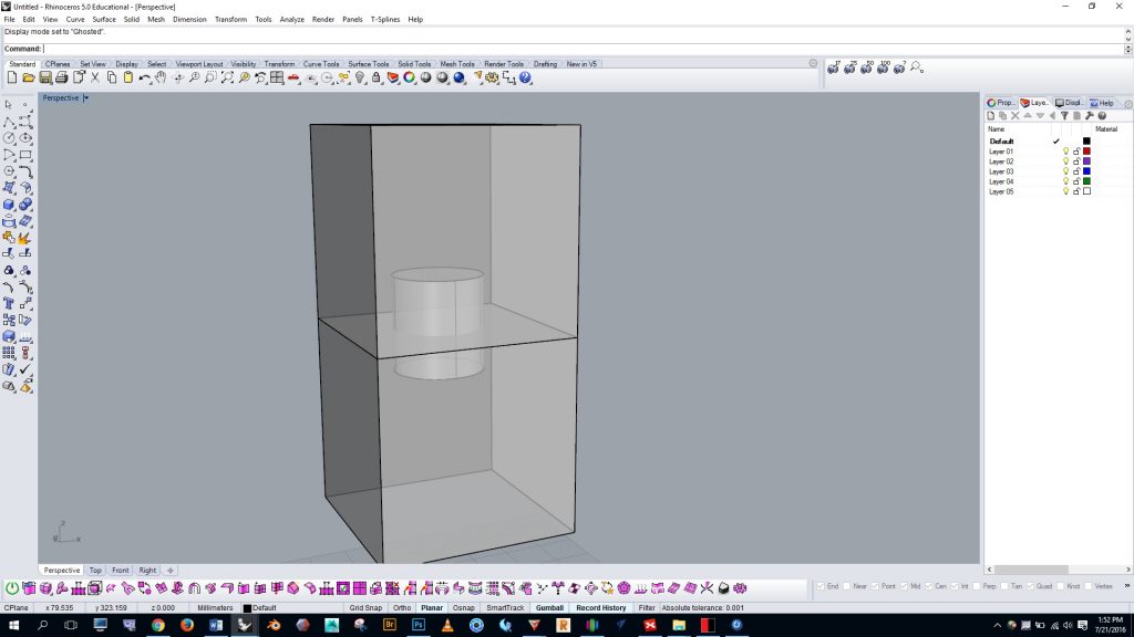
The example below shows the process of creating the holes and offset pins. We begin by creating two boxes…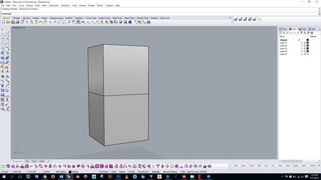
We create a cylinder in the center…
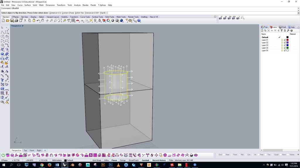
We select the cylinder and run the “offsetsrf” command, and choose to offset by .4mm…
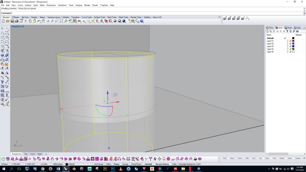
We select the outer cylinder and copy and paste it, and then hide the duplicate and the top box…
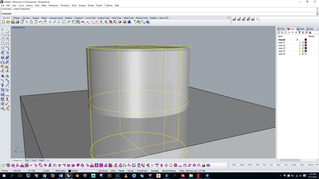
We then run the boolean difference command and delete the outer cylinder from the box…
Then we show the upper box and duplicate outer cylinder and run the boolean difference command on the upper box. Finally, we have a pin and two offset holes.
Making parts hollow in Rhino: why and how. In some situations you may want to make your project hollow to save material, lower the cost of printing, and/or reduce the weight of the print. Keep in mind that our FDM printers at the MakerSpace may have some difficulty with extremely thin walls. I generally keep my walls at least 4mm thick. Thinner walls can be achieved, but you may run into difficulty with them — especially if your project is large.
In the video below, Kyle Houchens tells why you may want to print hollow and shows how to create a hollow model.
Making parts hollow in MeshMixer. Getting a good offset interior surface can sometimes be difficult in Rhino. Sometimes it’s easier to make the part hollow in MeshMixer. To do this, first scale your model to the desired size in Rhino. Then open MeshMixer and import your part.
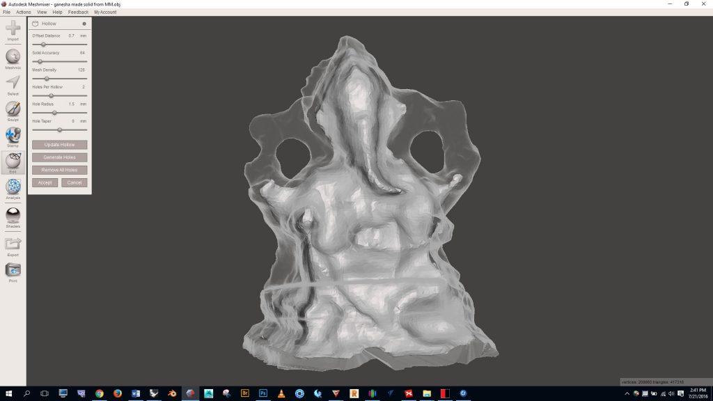
Click “edit”, select “hollow”, select the offset distance, etc.
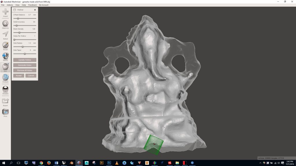
I suggest creating at least one hole in an inconspicuous spot. Without a hole you’ll have a closed form inside of another closed form, which can confuse the 3D printing program. The hole will help avoid any confusion. Notice in the image below the single green hole that will be created in the bottom. Once you’re happy with the settings click “accept” and you’ll have a hollow form. If you wanted to make further modifications to the form you could take it back into Rhino and edit it with mesh boolean processes.
Check if your form is solid– if it’s not, find the naked edges and close them up
To 3D print effectively, your part must be a closed solid. Another word that is used interchangeably with solid is watertight. A watertight part is closed along every edge and face. A watertight part would not leak if filled with (virtual) water. If there are openings in your part — even very small openings — the 3D printing software will get confused about where the boundary should be between the inside and outside of your part. Confused 3D printers do strange and undesirable things.
There are a few ways to check to see if a part is a watertight solid:
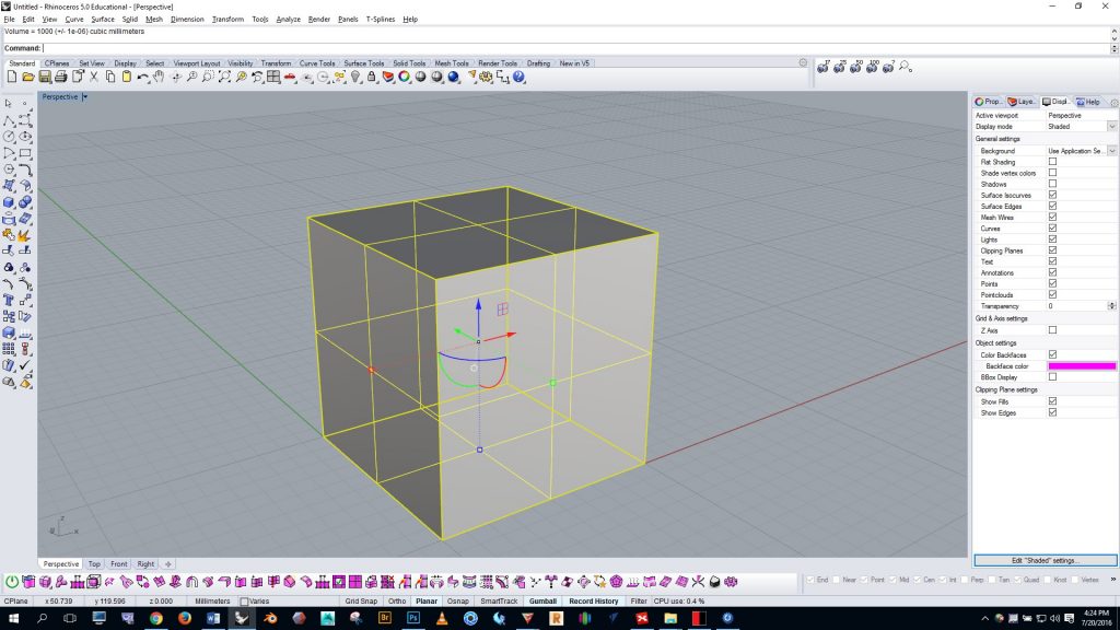
1) Run the volume command. Select your part and run the “volume” command. If a volume is displayed in the command line (as shown below) then your part is solid.
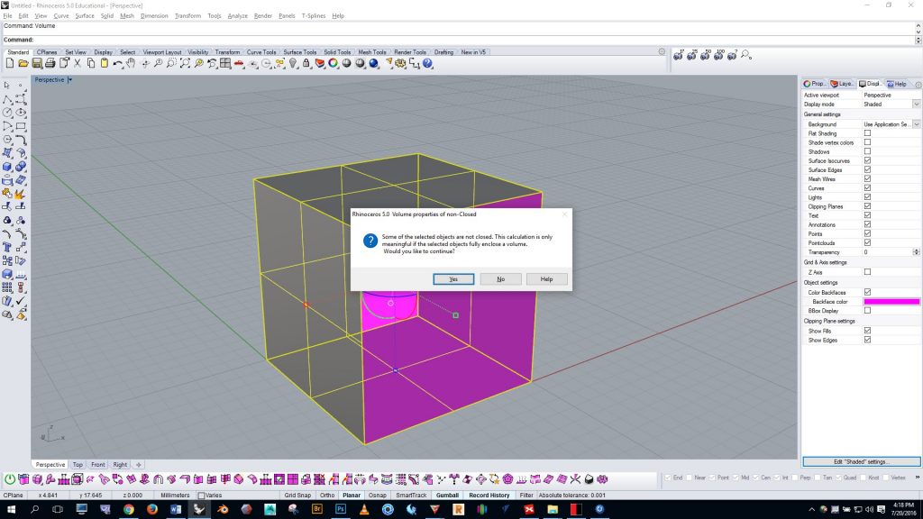
If, however, an error message pops up (as shown below) then your part is open.
2) Run the “what” command. Type “what” in the command line. Read the box that pops up. Look for the terms “closed solid polysurface” or “closed polygon mesh”. If, however, your part is described simply as a “valid polysurface” or an “open polygon mesh” then your part is open.
3) Selecting specific types of geometry. You can also run the “selopenmesh”, “selopenpolysrf”, “selclosedmesh”, “selclosedpolysrf” commands to select specific open or closed geometry.
If your part is open you can locate the problem area(s) by doing the following:
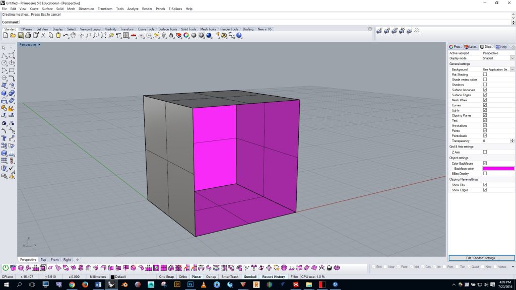
1) Adjust the display options. Change the display options in Rhino to color backfaces and choose a bright color. This will help you see where the openings are in the part. Notice in the image below how the open interior of the model becomes bright pink.
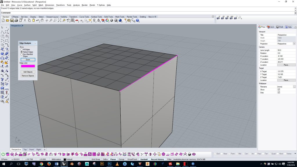
2) Find naked edges. Run the “showedges” command and select “naked edges”. This will turn naked unjoined edges bright pink (as shown below). For complex models it’s helpful to turn wireframe viewing mode on when using this command– this will help you find the naked edges more easily.
To close an open NURBS polysurface, you can try the following:
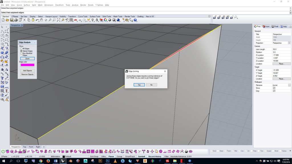
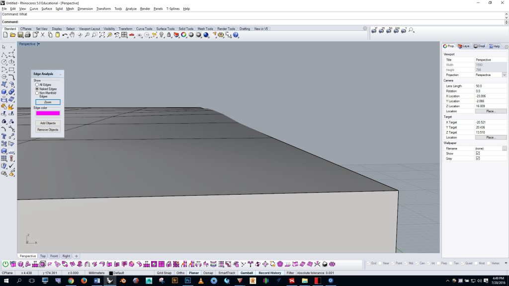
1) Run the join edge command. Use the “joinedge” command to join edges that are close but not fully touching. (as shown below)
This command does not always work. Be advised that when it does work there will be a moderate deformation in the geometry. See below:
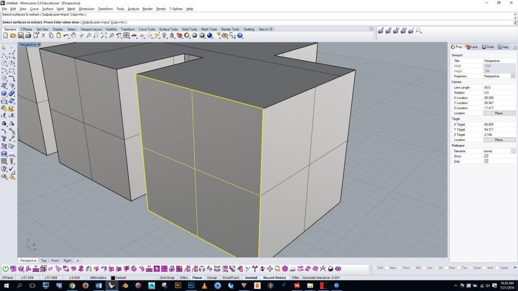
2) Extract the bad surface and redraw it. If the open edge is part of a simple face then you may want to simply delete and redraw it using your osnaps so that it will join properly. To select and remove a single surface from your model use the “extractsrf” command as shown below.
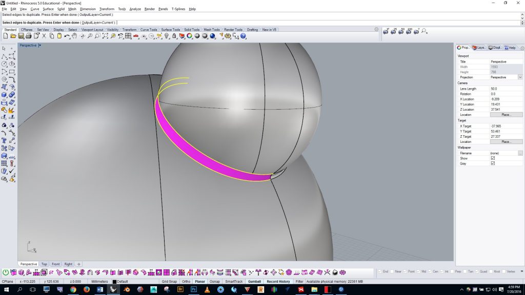
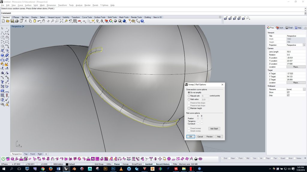
3) Duplicate edges and use the sweep2 command to close the hole. First, use the “dupedge” command to duplicate the unjoined edges around the problem area. See below:
Join the edges so that you have two long rail curves and one or two cross section curves. Then use the “sweep2” command to close the hole (see below). This command always requires two rails but it can work with one or two cross section curves, meaning that it can fill holes with four or three sides.
[return to 3D Printing Guide main page]
Save iterations of your project along the way
While modeling, we can sometimes encounter very difficult problems that are best solved by reverting to an earlier version of the project. It’s a good idea to save a new version of your file every half hour with “save as”. This will take up some room on your flashdisk or hard drive, but it will save you lots of frustration down the road.
[return to 3D Printing Guide main page]
Join the NURBS geometry into one single solid part
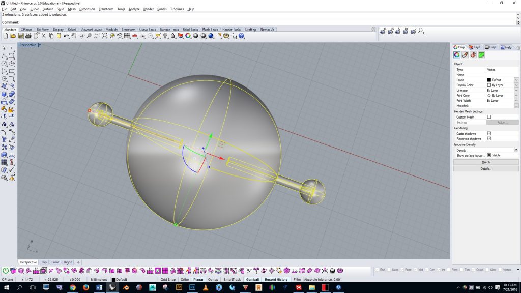
Make one single solid part. In Rhino we often design forms using many different solids and surfaces that intersect each other. During the design process, keeping things separate makes it easier to make changes, but when it comes time to print the design we need to join everything together into one single solid part. This is because overlapping solids (as shown below) will sometimes cause the printer to create a hole where the form should be solid.
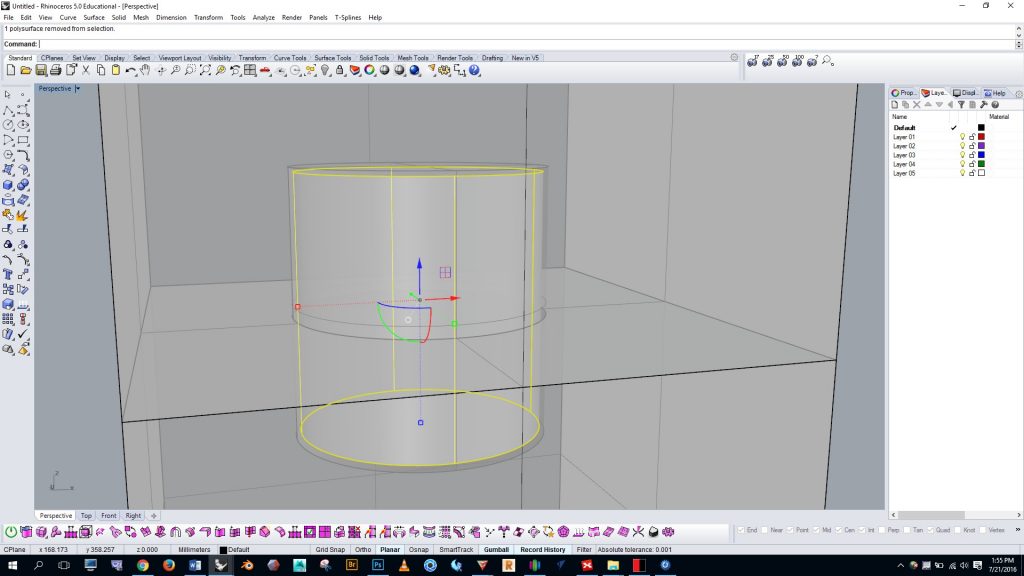
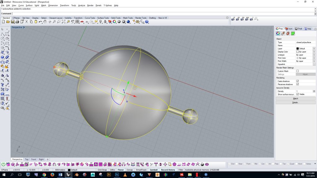
As you prepare to 3d print your project, you’ll want to boolean and/or trim and join the whole model together into single unified solid as shown in the example below. When we select this model, we see in the command line “1 polysurface added to selection”, which means our part is a single unified solid.
Use boolean operations and wirecut when working with solids. If you’re working with closed polysurfaces, try to avoid trimming them and use boolean operations instead– this will avoid creating open polysurfarces during the operation. Another good alternative to trimming is the “wirecut” command. Note that boolean operations and the wirecut command only work on solids.
Create the desired 3D form with NURBS geometry
To streamline your workflow and create good clean geometry that can be successfully 3D printed, do the following when modeling in Rhino:
Design in millimeters. If you model in inches you’ll have to deal with fractions, which can be cumbersome. Millimeters are easier. Also, the software we’ll use to create the 3d printing toolpath works with millimeters, so modeling in millimeters will streamline the export/import process.
Use osnaps when modeling to ensure that surfaces are properly joined.
Model with solids instead of open polysurfaces whenever possible.
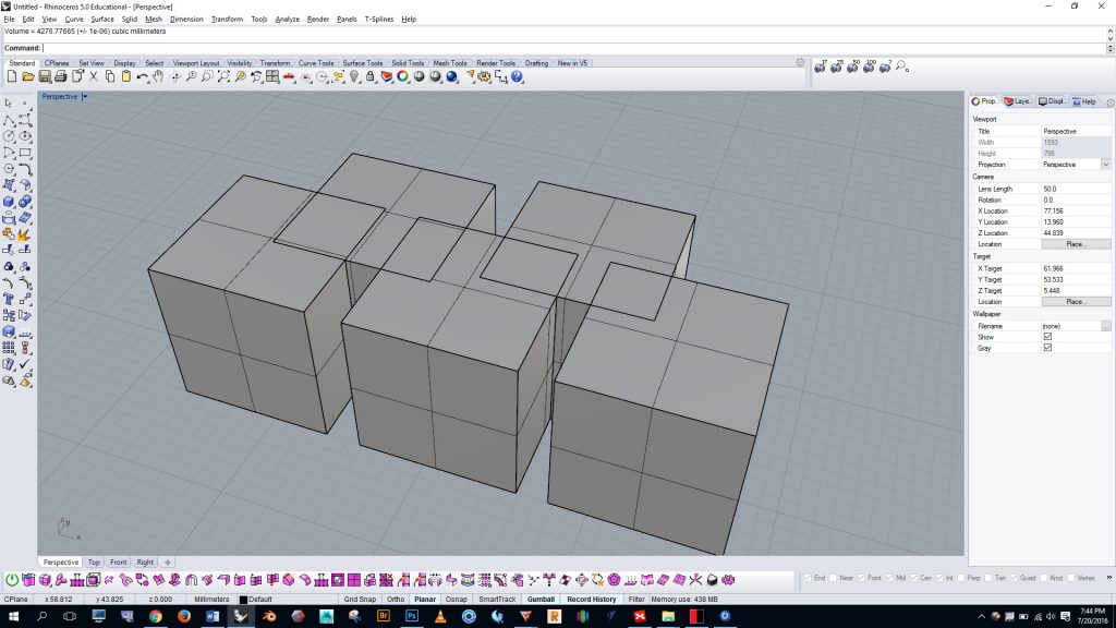
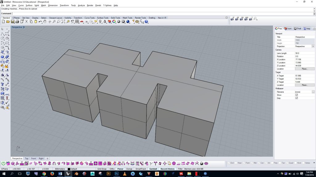
Merge coplanar surfaces. 3D printing programs sometimes get confused by adjacent unmerged surfaces in the same plane. Here’s an example to illustrate:
The example above is made of cubes of the same height that were overlapped and joined with boolean union, and the form is now one single solid. Notice, however, that top of the form still shows the edges from the separate cubes. To unify the top faces we can run the “mergeallfaces” command, and the result is below. This form will print successfully.
