Author: Joe Meiser
artsxpose Art21 option
In a typical semester, students enrolled in Digital Fabrication attend art events on campus in person to satisfy the artsxpose requirements. Because of COVID restrictions, many art events may be canceled. In light of the limited options this semester, students may satisfy an artsxpose requirement by watching an episode of Art21 and posting a written response. Instructions are below:
<1> Go to the Art 21 website (http://www.pbs.org/show/art-21/episodes/) and watch one hour-long episode. Choose the episode you find most interesting. (Note that there is a dropdown menu in the upper right part of the screen where you can select other seasons — there many episodes to choose from.)
<2> After you’ve watched the episode, submit a thoughtful ~ 200-word response to the class website in the “artsxpose” category. Describe what was covered in the episode and tell what you found interesting, surprising, and/or challenging about it.
Students should satisfy two artsxpose requirements in the first half of the semester, and two in the second half. Watching one episode and submitting the written response counts for one artsxpose.
links from Everest Pipkin
claire h http://www.clairesophie.com/
m p f http://plummerfernandez.com/
william chyr http://manifold.garden/
https://n-e-r-v-o-u-s.com/
sougwen chung – https://sougwen.com/project/
sofia crespo – https://www.instagram.com/
nicole aptekar – http://nicoleaptekar.com/
auria harvey – http://auriea.org/
https://arambartholl.com/
http://www.morehshin.com/
good ol trevor http://www.paglen.com
this whole show – > https://bitforms.art/
but particularly sophie khan https://www.sophiekahn.net/
joanie lemercier https://joanielemercier.com/
drone sculptures.. http://www.studiodrift.com/
queen nefertiti’s head -> https://hyperallergic.com/
Tammy Troup’s Intellectual Property presentation
Keycode for Sculpture Lab door: 3270#
Heath Hansum project March 2018
test
[expand title=”What is Lorem Ipsum?“]Lorem Ipsum is simply dummy text of the printing and typesetting industry. Lorem Ipsum has been the industry’s standard dummy text ever since the 1500s, when an unknown printer took a galley of type and scrambled it to make a type specimen book. It has survived not only five centuries, but also the leap into electronic typesetting, remaining essentially unchanged. It was popularised in the 1960s with the release of Letraset sheets containing Lorem Ipsum passages, and more recently with desktop publishing software like Aldus PageMaker including versions of Lorem Ipsum.[/expand]
[expand title=”Why do we use it?“] It is a long established fact that a reader will be distracted by the readable content of a page when looking at its layout. The point of using Lorem Ipsum is that it has a more-or-less normal distribution of letters, as opposed to using ‘Content here, content here’, making it look like readable English. Many desktop publishing packages and web page editors now use Lorem Ipsum as their default model text, and a search for ‘lorem ipsum’ will uncover many web sites still in their infancy. Various versions have evolved over the years, sometimes by accident, sometimes on purpose (injected humour and the like).[/expand]
[expand title=”Where does it come from?“] Contrary to popular belief, Lorem Ipsum is not simply random text. It has roots in a piece of classical Latin literature from 45 BC, making it over 2000 years old. Richard McClintock, a Latin professor at Hampden-Sydney College in Virginia, looked up one of the more obscure Latin words, consectetur, from a Lorem Ipsum passage, and going through the cites of the word in classical literature, discovered the undoubtable source. Lorem Ipsum comes from sections 1.10.32 and 1.10.33 of “de Finibus Bonorum et Malorum” (The Extremes of Good and Evil) by Cicero, written in 45 BC. This book is a treatise on the theory of ethics, very popular during the Renaissance. The first line of Lorem Ipsum, “Lorem ipsum dolor sit amet..”, comes from a line in section 1.10.32.[/expand]
Machine design automata
polyhedron lasercutter exercise
Process for using the Slicer app to lasercut a cardboard polyhedron
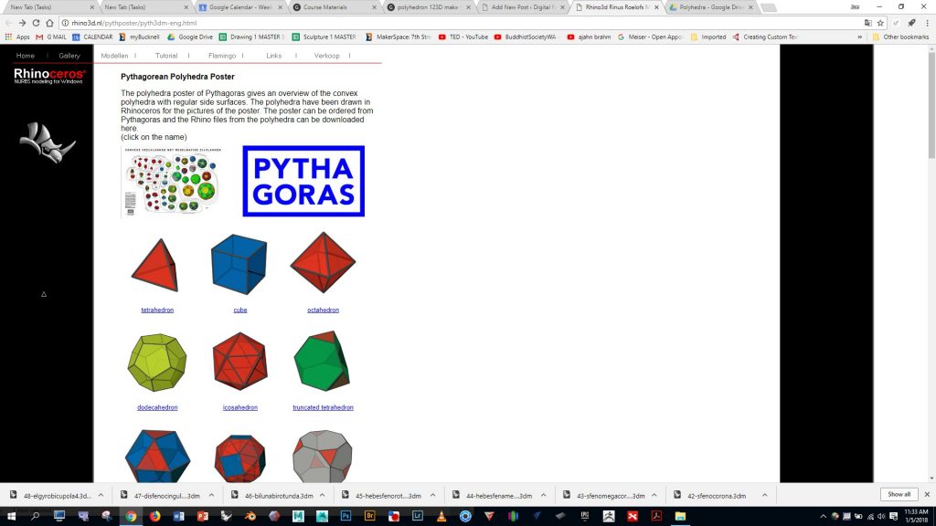
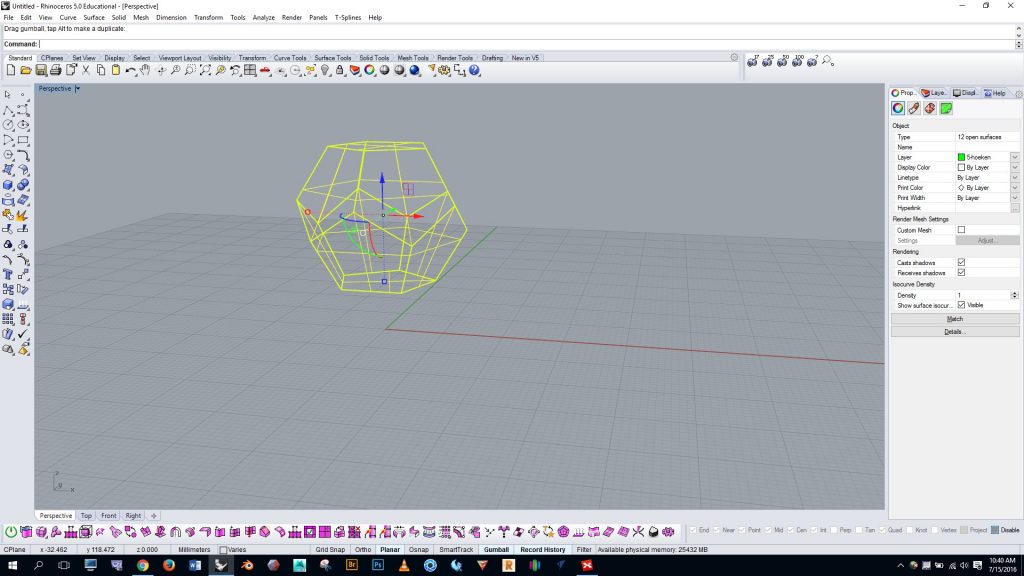
Go to http://rhino3d.nl/pythposter/pyth3dm-eng.html Choose and download a polyhedron. (Note: these polyhedra are also available here on Google Drive)
Open Rhino using a “small objects – millimeters” template, and import the polyhedron you’ve downloaded
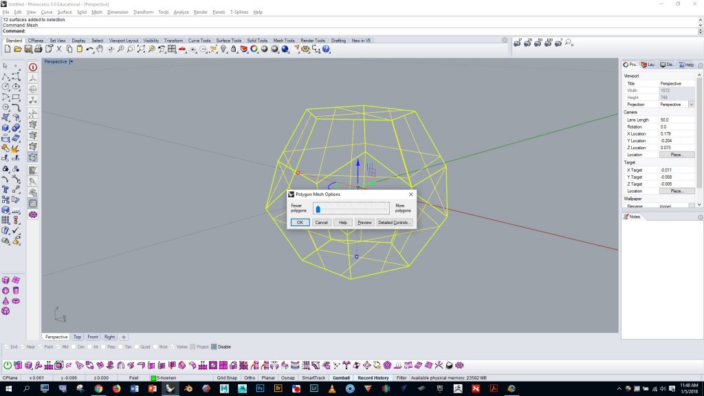
Select your polyhedron and run the “mesh” command with simple controls. Drag the slider all the way to the left.
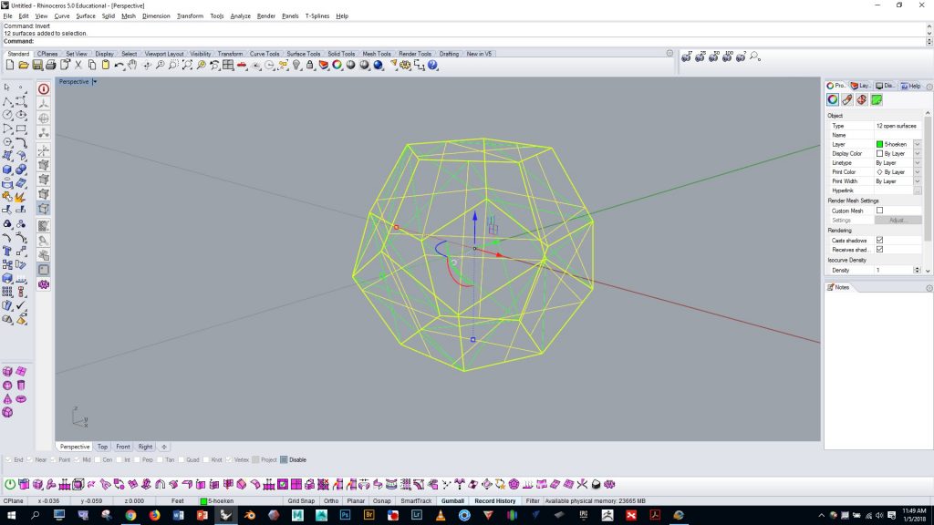
Run the “selmesh” command to select the mesh you just generated. Run the “invert” command and press the delete key. This will get rid of the original NURBS form that you imported.
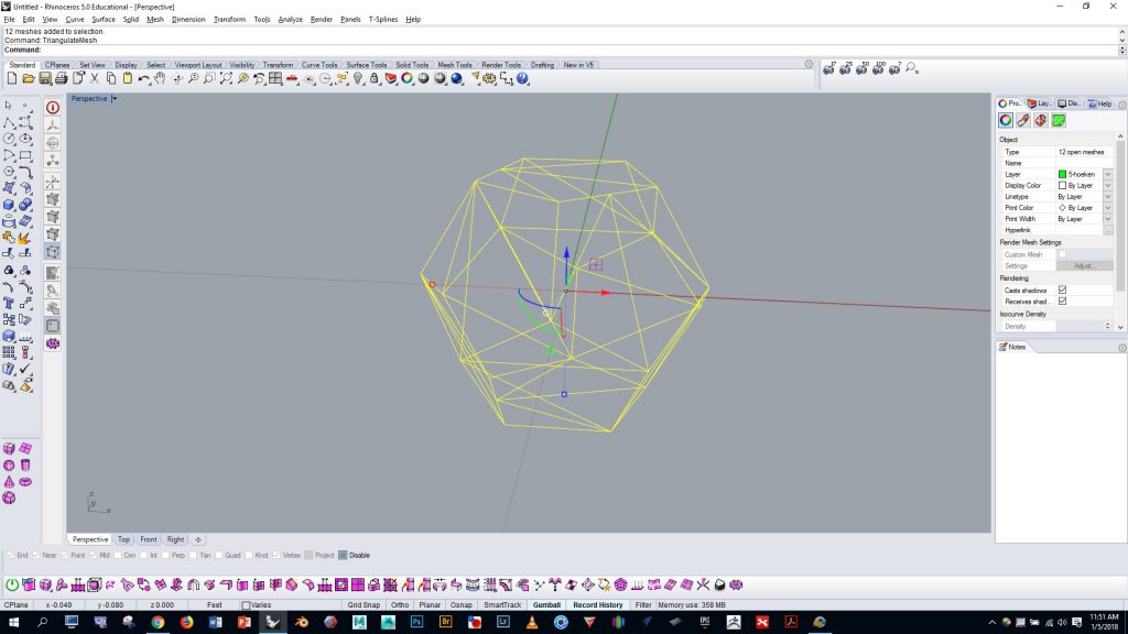
Now select the mesh and run the “triangulatemesh” command. This will ensure that your polyhedron mesh will import properly to the next program.
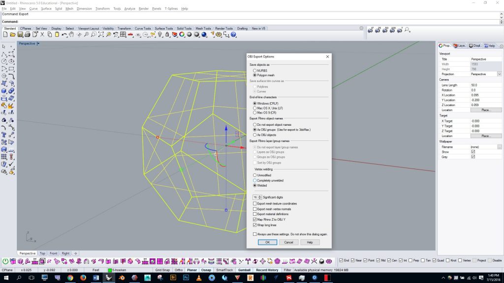
Export the polyhedron as an OBJ with the settings shown
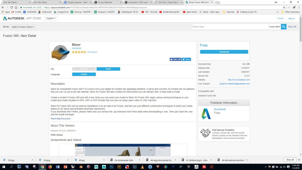
Download, install, and open the Autodesk Slicer App on your computer by following this link: https://apps.autodesk.com/FUSION/en/Detail/Index?id=8699194120463301363&os=Win64&appLang=en
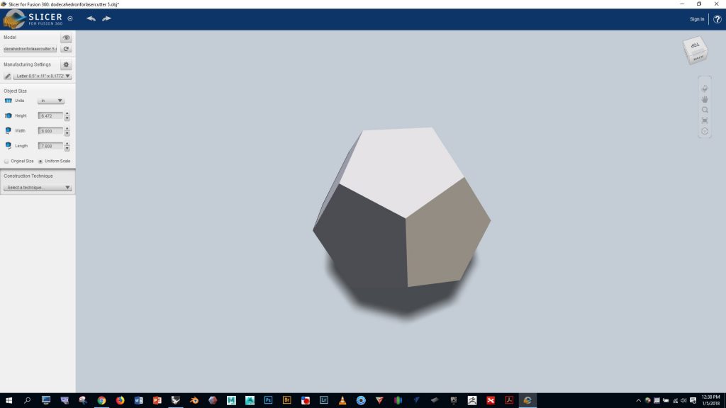
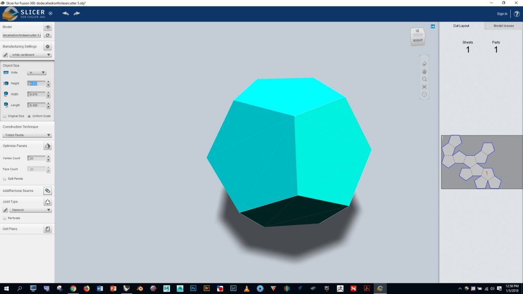
Import your OBJ file
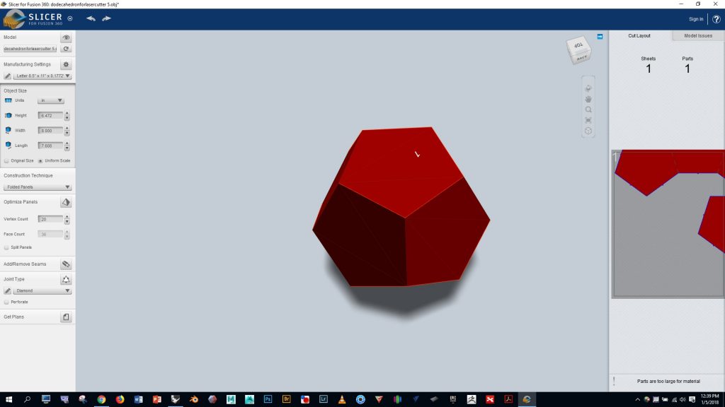
Select “folded panels” from the dropdown option on the left and notice that the program automatically generates a cut pattern for us which we can see on the far right
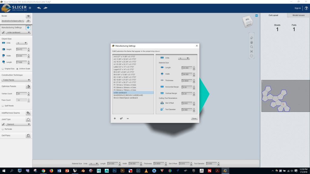
We’ll be working with the thin white cardboard that’s available in the Mooney Lab. Let’s configure Slicer to work with the dimensions of this material by doing the following:
- click on “manufacturing settings” pencil on the left side
- Click the + button in the lower left to add a new material
- Name the new material “white cardboard”
- Enter the values shown in the image below
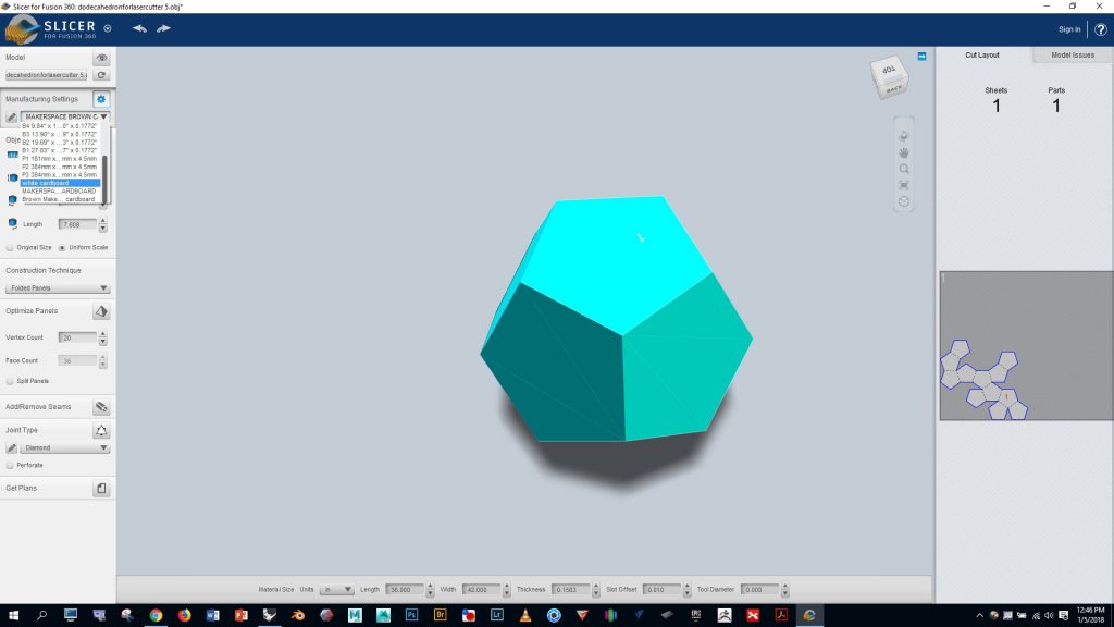
Click the little dropdown arrow on in the manufacturing settings window and select the “white cardboard” option we just created
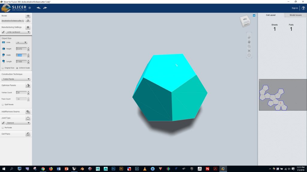
Notice on the right that our polyhedron is quite small relative to the sheet of cardboard. Adjust the values in the “object size” box to make the polyhedron larger on the cardboard
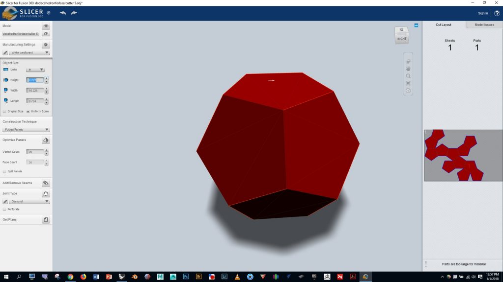
Notice that setting the object size too large will turn the whole polyhedron red, indicating that the whole pattern won’t fit on the single sheet of cardboard. Adjust as needed to make it fit on the cardboard and turn it blue.
If you’d like to improve upon the automatic fold pattern generated by Slicer to make assembly simpler and/or make better use of the cardboard, click on the little razor icon in the lower left, and follow the instructions.
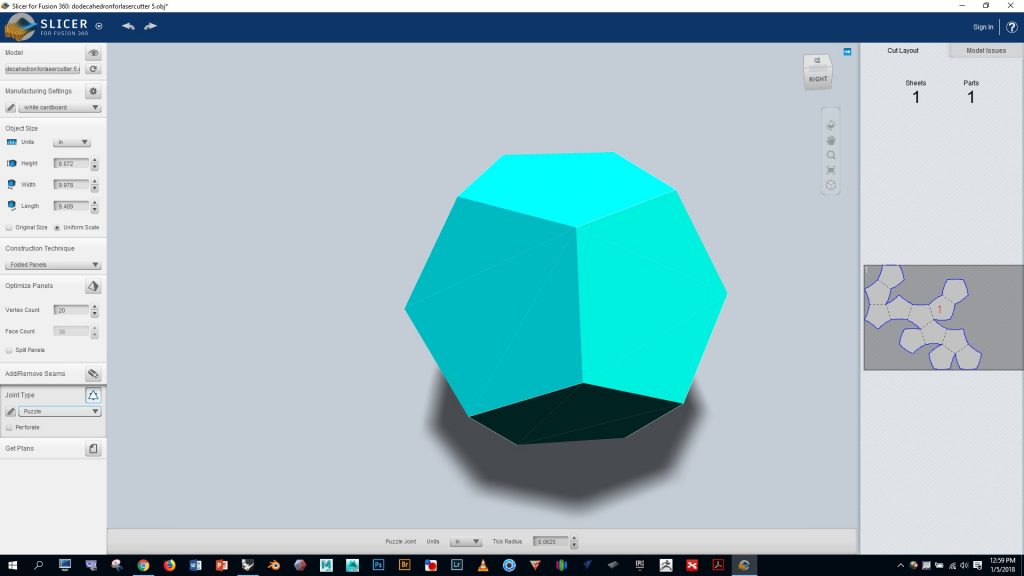
I used “puzzle” for the joint type, and found that it worked well for assembly
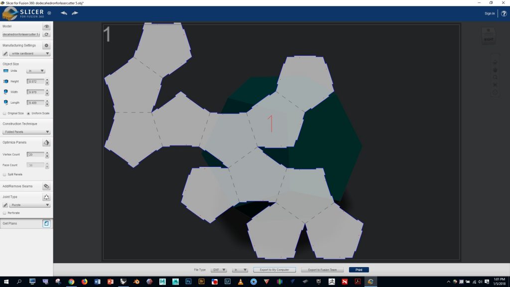
Click the “get plans” button at the bottom and export your project as a DXF file
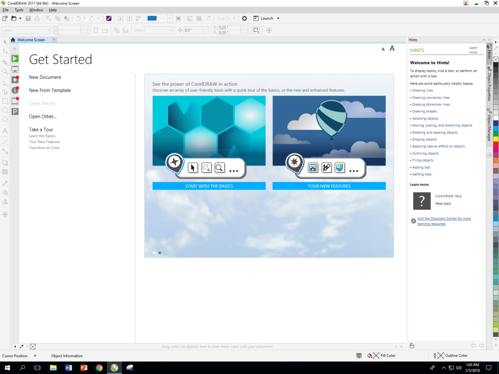
In the Mooney Lab, log on to the computer by the lasercutter and open Corel Draw (you can skip the info request screen)
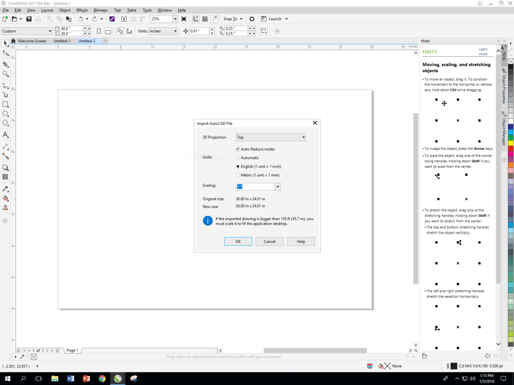
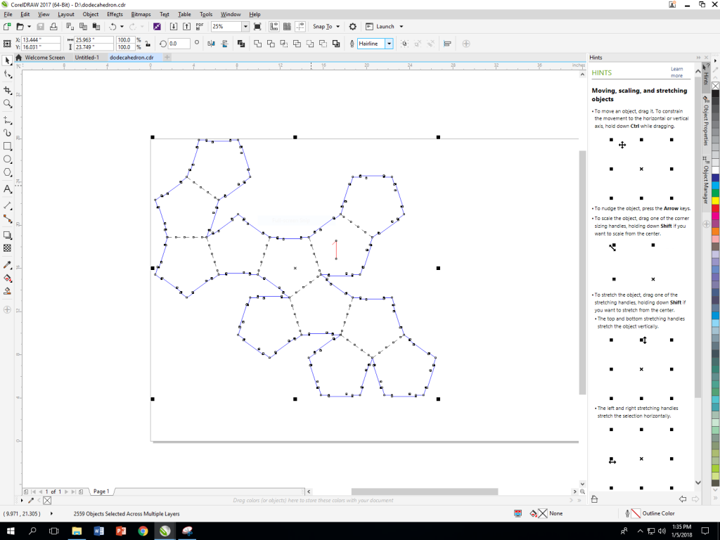
Click on “file”, then “new”, and enter a width of 40″ and height of 28″. Now go to “file” > “import”, and select your DXF file with the settings shown below, and press OK
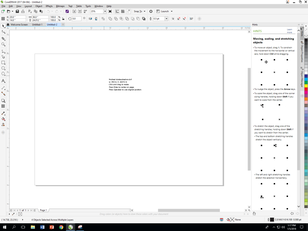
You’ll be prompted to draw the location and size of your object. We want to keep the size the same as it was in Slicer, so click the spacebar to use original position.
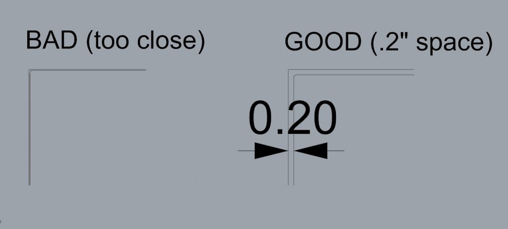
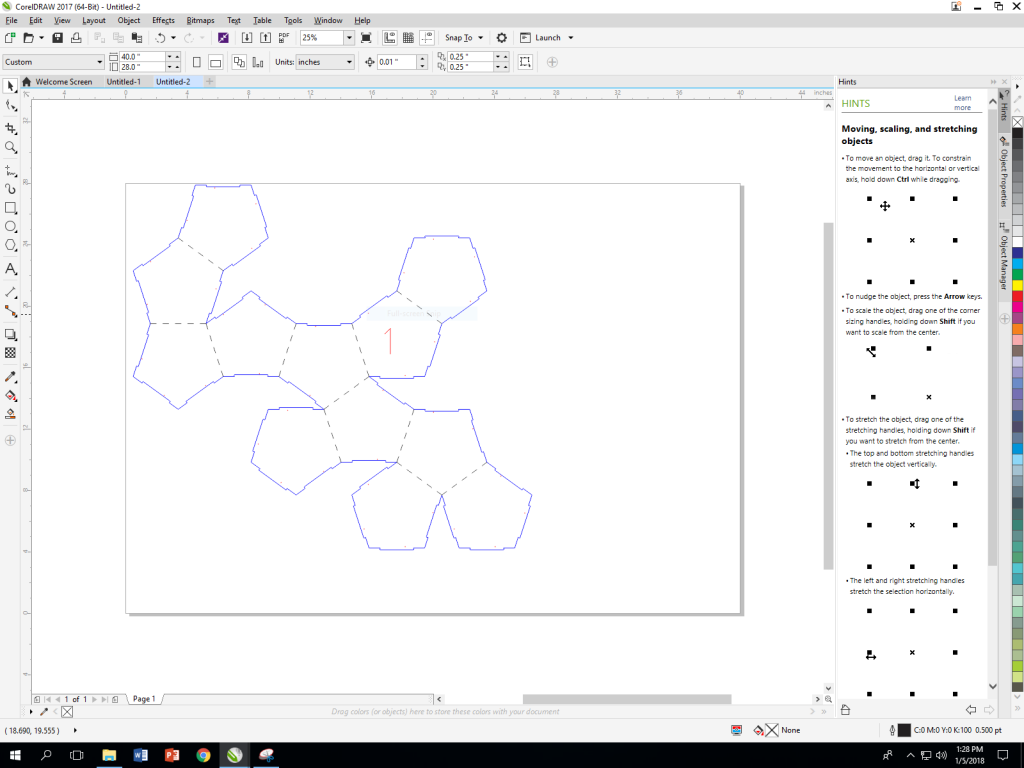
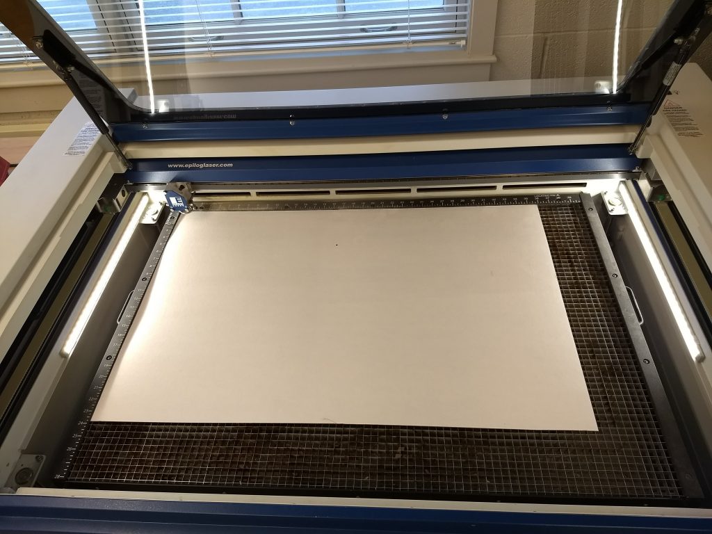
Move your design into the top left corner by adjusting the X and Y object position numbers in the top left of the screen. Your design must be within the bounds of the material by at least 0.2 inches. Otherwise, the laser could hit the rulers in the bed of the machine. Look at the images below to understand what this means more clearly.
We don’t need the rectangular border lines, so let’s select and delete them
Draw a lasso selection around all of your lines and then set the cutting width to “hairline” in the dropdown menu at the top. Making this selection is important because it will cause your lines to be vector cut rather than rastered.
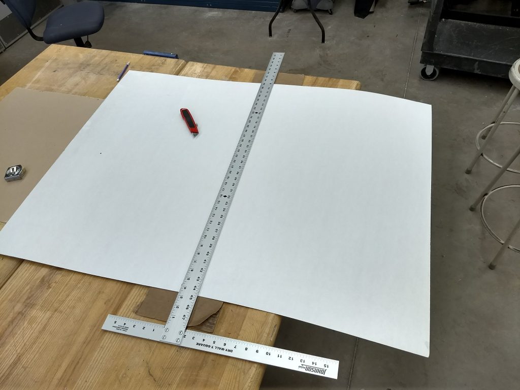
Now we’re pretty much ready to use the lasercutter. But we will first need to cut our cardboard down. Our full sheets of the white cardboard are 36″x48″, and we want to cut the sheet in half to match our drawing at 36 x 24″. Measure and cut carefully using the tools in the Mooney Lab.
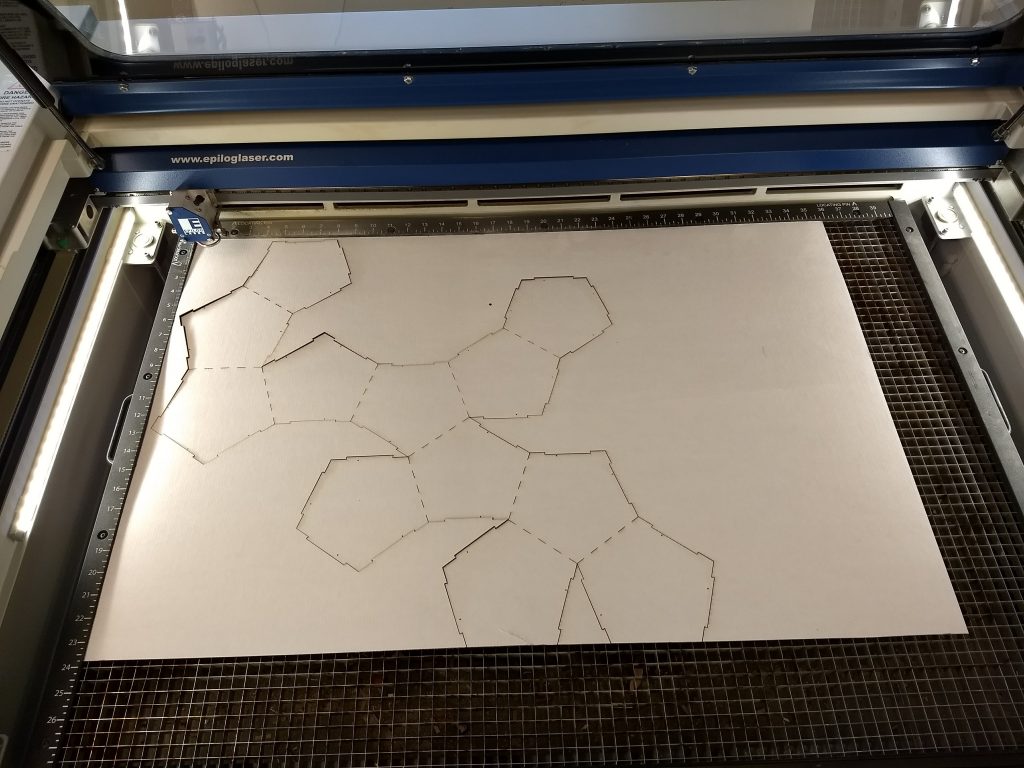
Now have the Mooney technician help you cut your design with the lasercutter. The following settings should work well for the material we’re using:
- Piece size: 40 x 28″
- Speed: 40
- Power: 100
- Frequency: 50
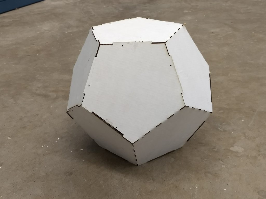
Once your pattern is cut out, after a bit of folding and some hot glue your finished polyhedron will look like this:
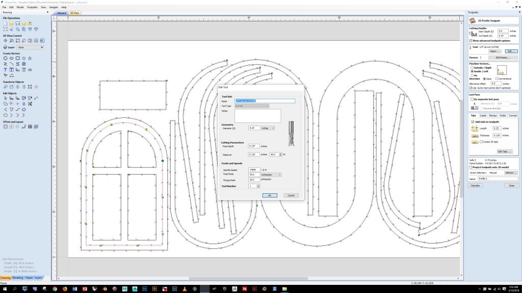
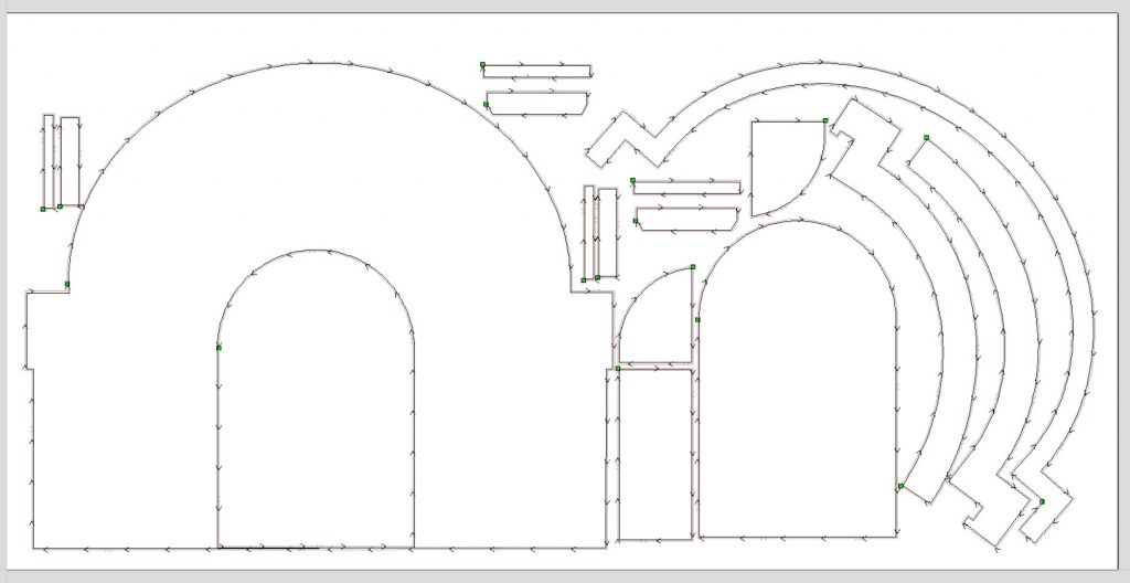
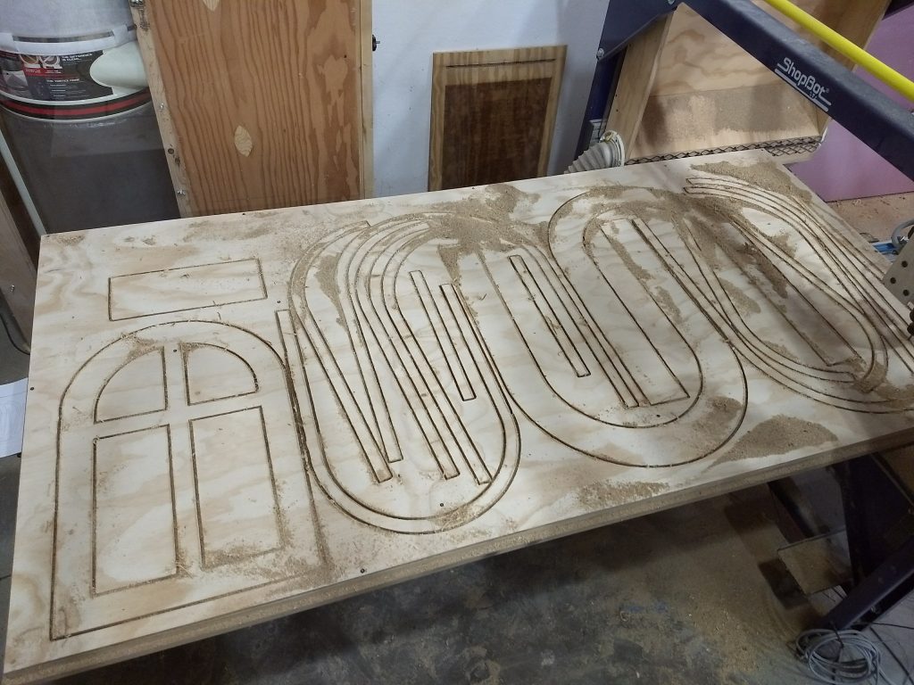
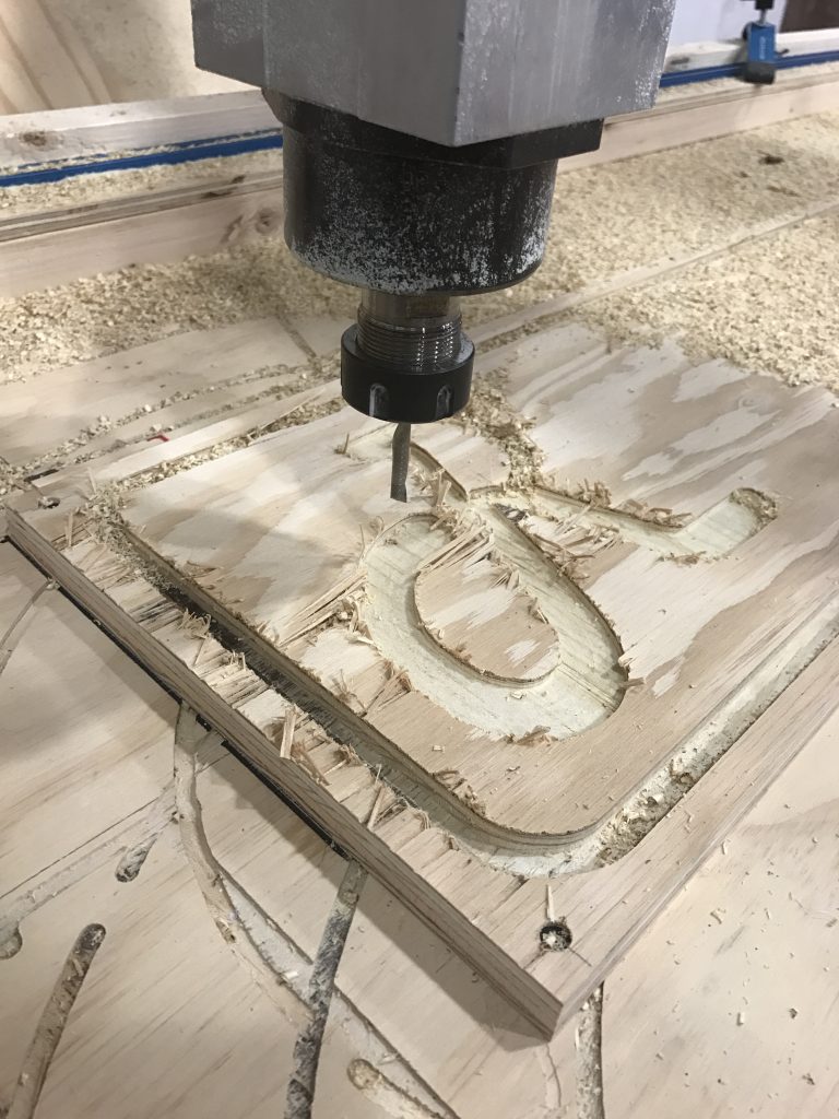
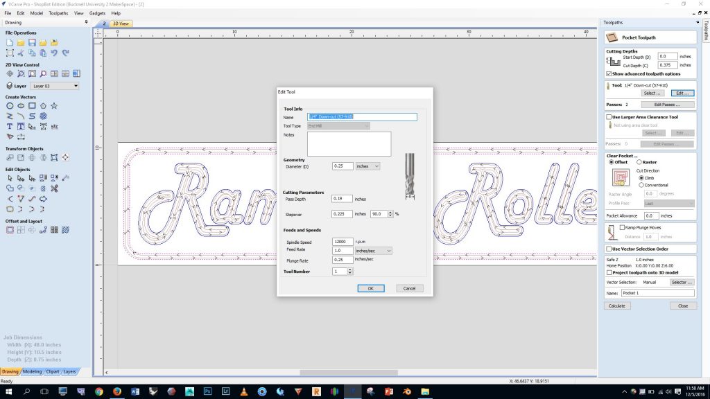
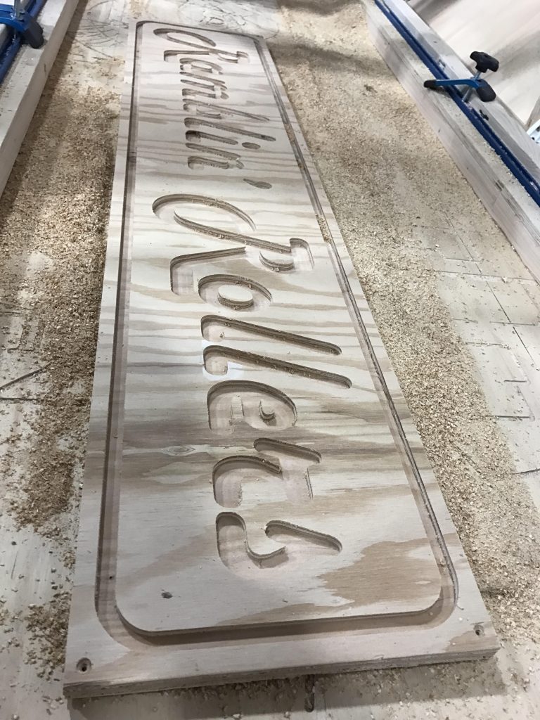
CNC notes
Intro to Mudbox
First, watch this video:
A FEW NOTES ON BASE MESHES
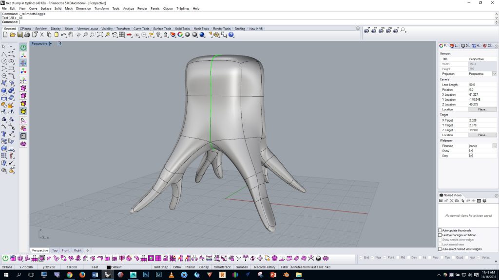
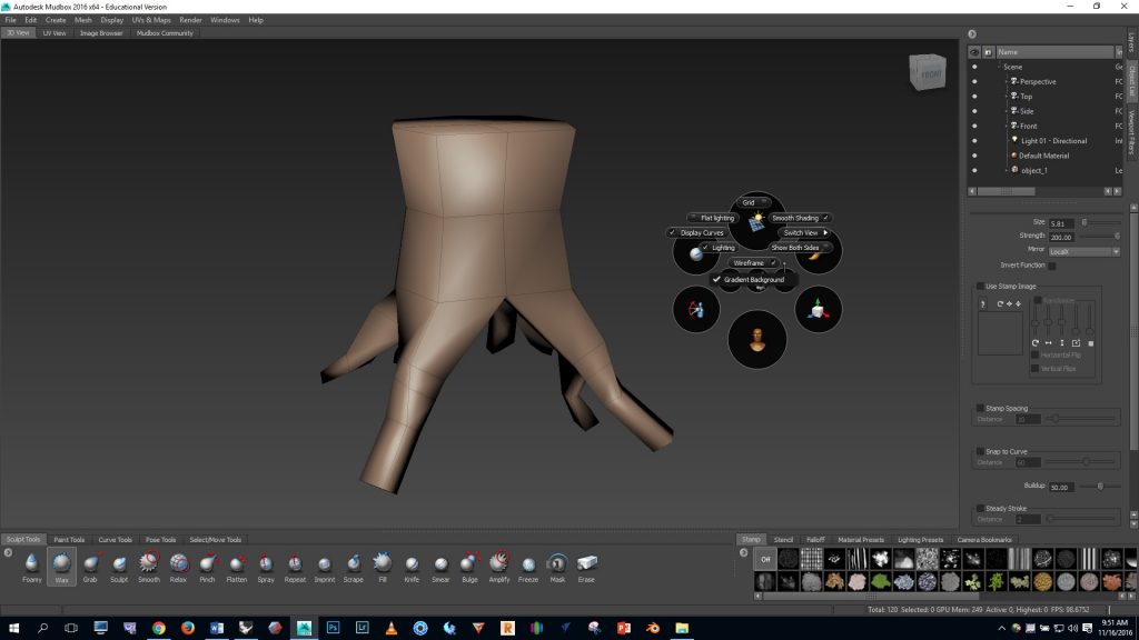
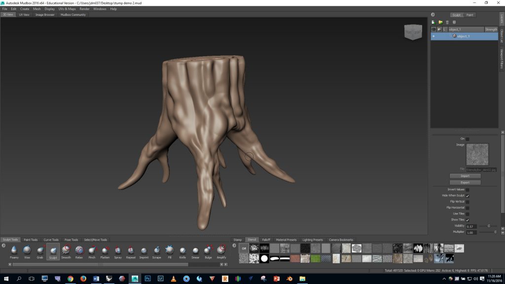
In CAD, a “base mesh” is a simple, low poly mesh that we use as a starting point for CAD sculpting. In this exercise you’ll use the base mesh of a tree stump that’s shown below as your base mesh, and you’ll detail it in Mudbox. Notice that the base mesh shown below is composed entirely of “quad” faces (four-sided polygons)—quads are important for efficient subdivision in Mudbox. We must avoid three-sided, five-sided, six-sided, etc. faces when working with subdivisions in Mudbox.
IN MUDBOX
Download the Professor’s base mesh of the stump by clicking here.
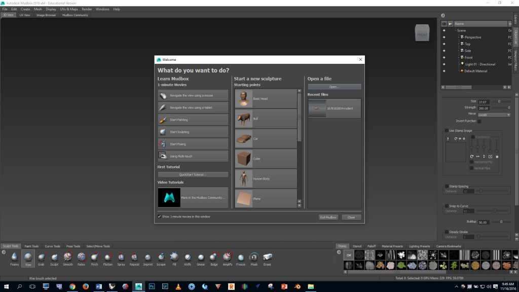
Open Mudbox, click the “open” button, and select the OBJ file for the base mesh.
Hold the space bar and notice that a menu pops up. Click on the top button. Notice that you can turn the grid and wireframe on and off.
Hold the space bar again and click on the center button, then click on “mirror”, then make sure that “local x” mirroring is ON.
Viewport navigation in Mudbox:
- Orbit with right mouse button and ALT
- Zoom by rolling the middle mouse button
- Pan with the middle mouse button and ALT
Press SHIFT D a few times and notice in the top right corner that we’ve added a few levels of subdivision which smooths the base mesh. Now by clicking PAGE UP or PAGE DOWN we can increase or decrease the level of subdivision. If we want to make big adjustments to the geometry we should work on a low level. If we want to add fine details we work on high level.
Notice in the bottom left that we have a number of brushes to choose from. Click on the GRAB brush and then mouse over the model.
We can change the SIZE of the brush by holding B and dragging the left mouse button UP or DOWN — We can change the STRENGTH of the brush by holding M and dragging the left mouse button UP or DOWN
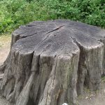
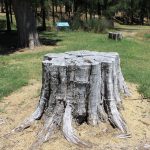
Let’s refer to these visual references as we add detail:
Use the GRAB brush to make big adjustments to the form of the roots and trunk.
Select the BULGE brush and use it to make lumps in the roots and bulged areas on the trunk.
Now let’s use the SCULPT brush to do some sculpting and add detail. If you click on the FALLOFF tab on the lower right you’ll see that we can adjust the type of mark the brush will leave. In this case I found that the #2 option worked best for my purposes.
Notes:
- After you create some marks with the SCULPT brush you can SMOOTH the surface by holding the SHIFT key.
- If you want to make an INVERTED mark with the brush you can hold CTRL.
- At this point I felt that symmetry was making the stump look too regular so I turned MIRRORING off.
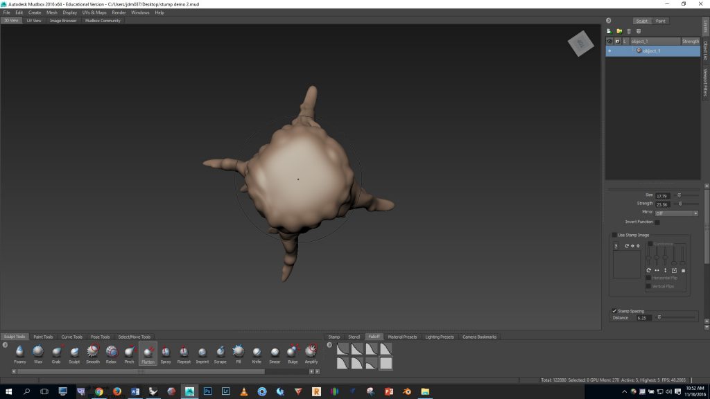
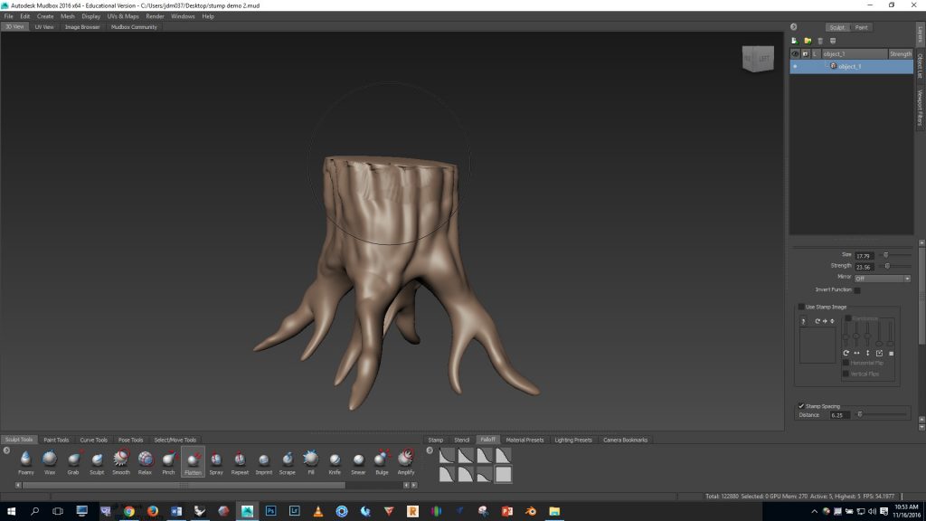
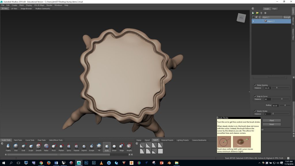
To flatten the top of the stump I selected the FLATTEN brush and used a FALLOFF option 7. Then I orbited so I was looking at the stump from above and smooshed the top down.
You can see that the top edges got a bit messed up. I fixed this by smoothing with the SHIFT key.
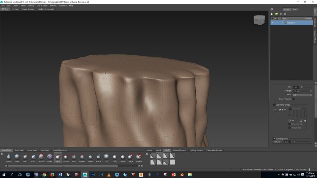
The top indents needed to be pushed in. I did this with the SCULPT brush, a sharp #1 FALLOFF, and by holding CTRL to use the INVERTED brush. Then, to make the top edge even sharper I then used the PINCH brush.
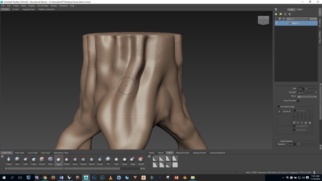
The PINCH brush was also useful for creating sharper creases along the side of the stump.
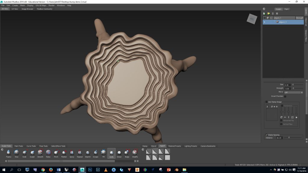
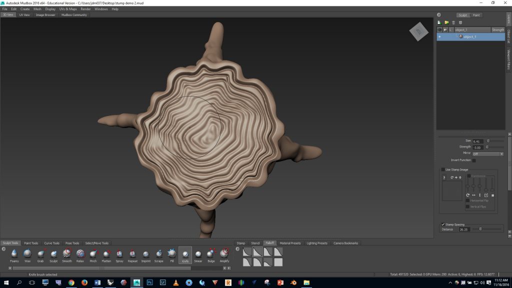
Now let’s add the rings on the top. Add a couple extra levels of subdivision by pressing SHIFT D. Then select the KNIFE brush and use a brush size of .3 and strength of -3. Go to the top view and work from the outside in.
I used the STEADY STROKE brush setting with a distance of 1 (see the settings panel, lower right). Steady stroke helps draw straight lines.
I felt that the regularity of the deep cuts looked unnatural so I smoothed with the SHIFT key.
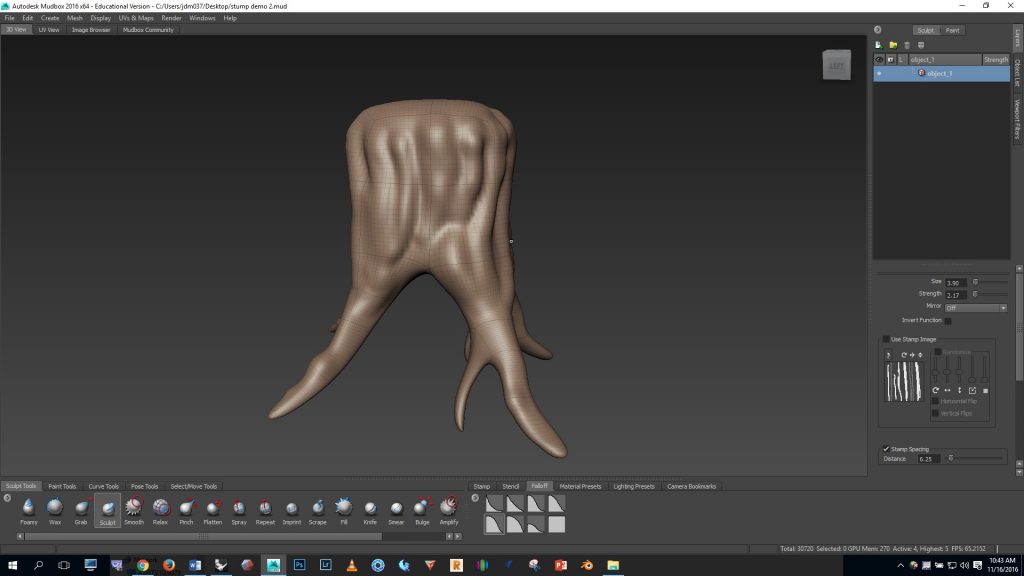
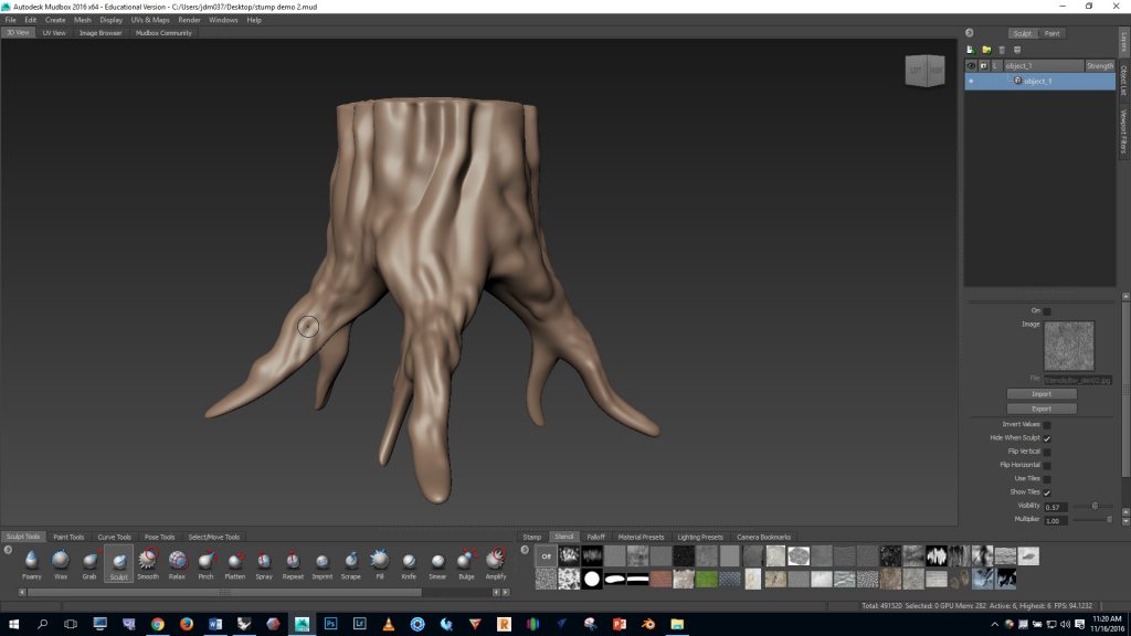
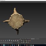
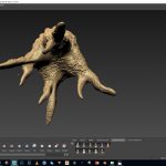
Here are some images of the fully sculpted form.
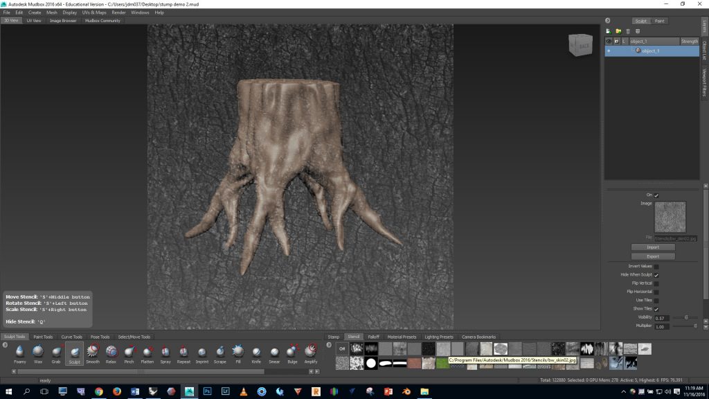
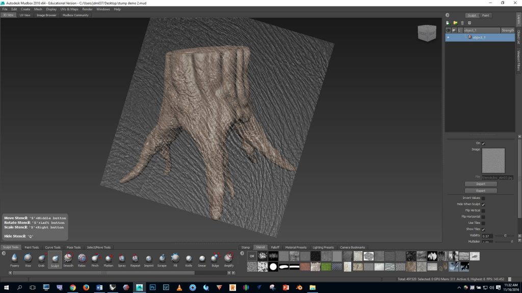
Now let’s add some bark texture. Click on the STENCIL panel, bottom right and select bw_skin02. PAGE UP to your highest level of subdivision. Notice in Mubox that there are instructions about how to alter the stencil in the lower left corner of the screen.
Experiment with using some of the other stencils to create variation in the texture.
The finished result is shown below. Your stump should be at least as detailed and complex as this example.
https://youtu.be/96BVkDyPsu4
To learn more about Mudbox:
A more comprehensive overview of Mudbox is available on Lynda.com. To access these videos, log on to your Lynda.com account using your Bucknell credentials. Then watch these videos.
Bunny Screenshots
Finished model:
Process images:
T-Splines introductory exercises
T-Splines Crash Course
The T-Splines crash course file can be found HERE. You’ll need to download this file to your desktop, extract the contents, then open the Rhino file contained within the folder.
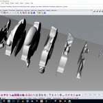
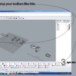
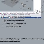
For easy access, here are screenshots of some of the first instructions covered in this crash course:
Notes:
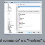
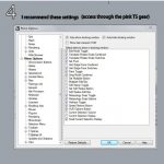
- To load the TSplines toolbars, type “options” in the command line > go to toolbars > click on t-splines > click the “all commands” box … this will show the program
- T-Splines will run only with the 64 bit version of Rhino — if the T-Splines toolbar isn’t showing up it may be because you launched the 32 bit version of Rhino
For more information, refer to the T-Splines user manual, or the starter guide.
T-Splines Bunny Exercise
Images:
Video:
If video fails to load, click here: http://digitalsculpture1.blogs.bucknell.edu/t-splines-introductory-exercises/
class photos
Meshmixer Hybrid Object Project Outline
Project summary:
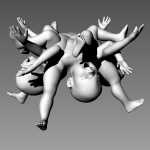
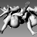
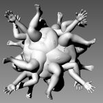
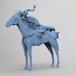
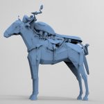
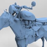
- To practice during the first class, download files from the Google 3D Warehouse and use Meshmixer to create at least two different hybridized forms; post screenshots of your two forms to the public class website. 3D scan one or more objects, then download one or more files from the Google 3D Warehouse. Use Meshmixer to combine two or more items to create an ambiguous sculptural form that can be visually understood in different ways, as shown in the examples above. Make a photorealistic render of your form with Keyshot. 3D print the form.
3D scanning:
- You can use 123D Catch, the Kinect in the MakerSpace, and/or the NextEngine scanner in the MakerSpace to 3D scan your objects.
- Click here to see examples of scans that were created using these three methods.
- 123D Catch – This program is installed on the Coleman 220 Lab computers. This tutorial shows how the process works.
- The Kinect scanner – Keep in mind that the Kinect does not do a good job of picking up fine details or small forms. This scanning method should only be used on large objects. Small objects should be scanned with 123D Catch photogrammetry or the NextEngine scanner. This tutorial shows how the Kinect can be used to scan your object.
- The NextEngine scanner – This tutorial shows how the NextEngine scanner can be used.
Google 3D Warehouse:
- Access the warehouse at: https://3dwarehouse.sketchup.com/index.html
- Download files in the oldest available SKP format
- Import the SKP file into Rhino > inspect the mesh; if it consists of quads then run the “triangulate mesh” command > export in OBJ format
- You can then open the OBJ in Meshmixer
MeshMixer:
- This tutorial shows how Meshmixer can be used to cleanup holes in your scanned objects.
- Watch these intro videos as you’re getting started with Meshmixer.
“Converge: Ghraib Bag” was included in the Museum of Art & Design’s “Out of Hand: Materializing the Post Digital” exhibition. This project consisted of the sculpture shown above and the animation included below.
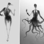
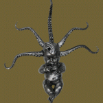
Hybrid examples — see also: “strange hybrid sculptures” google image search
Using Makehuman and Blender to work with human forms
Makehuman
Basic method:
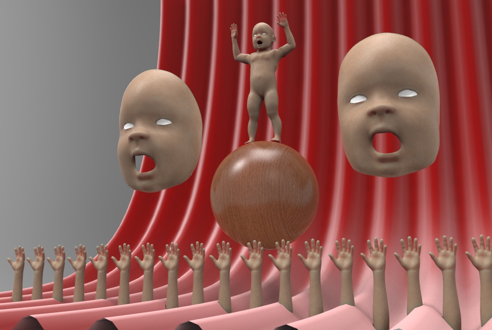
To avoid the step of adding the custom files, you can simply work with a basic male, female, or baby figure that the professor created. These figures are all saved in Blender format, so you can open them directly in that program. Note that the figures rigged with MHX are easier to pose. Access the basic figures here.
Advanced method (not recommended for students):
This free program can be used to generate a custom human figure that you can then pose in Blender. To use this program in your workflow, a few custom files have to be installed on your computer to allow MakeHuman to export in the correct format and allow Blender to import–the installation of the custom files is outlined on this site: https://thomasmakehuman.wordpress.com/mhx2-documentation/
Once the custom files are installed, do the following to create a custom human figure:
Go to the start bar and launch Makehuman
Use the program to customize a human figure
When finished, click: files > export > and select Blender exchange (mhx) format
Enter a file name and click the export button
Blender
- Go to the start bar and launch Blender
- Right click on the startup cube and delete
- If importing from Makehuman, go to file > user preferences > addons > and under import/export, click to activate Makehuman imports, then close user preferences
- Go to file > import > mhx > and locate the file you exported from Makehuman (On my machine, exported files go to documents > makehuman > export) Select your file > click the import MHX button at the top right
- After you’ve done this, your figure should be loaded
- The controls in Blender are much different than in Rhino. Here are the most important controls:
- Orbit with middle mouse button
- Pan with middle mouse button and shift
- Zoom by rolling middle mouse button
- Select with right mouse button
- Zoom selected by pressing the . button on the numberpad
- 5 toggles orthographic viewing mode
- 1,2,3,4,6,7,8,9 will show front, right, top views, etc.
- To pose:
- Right click on a pose handle
- Once a handle is selected, press G to translate
- Press Z, X, or Y to constrain movement
- With a handle selected, press R to rotate
- *Notice that translations and rotations are impacted by your point of view. Compare the results you get when looking from the front, side, top, etc.
- Move to new location and press left mouse button to apply
- Undo with CTRL Z
- More information on moving in Blender can be found here: https://docs.blender.org/manual/en/dev/editors/3dview/object/editing/transform/basics.html?highlight=transformations
- To export:
- First, save as a blender file in case you need to return to the file later.
- Next, go to file > export > OBJ
- Helpful links:
- Working with MakeHuman and Blender: https://www.youtube.com/watch?v=kPYbdnPwHuQ
In Rhino
- File > Import
- Mesh can be point-edited by pressing F10, but since meshes are difficult to edit, this is only really effective for deleting unwanted body parts.
- To further edit the figure it is best to use Meshmixer. Remember that Meshmixer will only import triangulated meshes. In Rhino, select the figure and run the “triangulatemesh” command before exporting to Meshmixer.
Meshmixer intro videos
Keyshot license server is: 27010@stout.bucknell.edu
survey
Using Meshmixer to cleanup a model
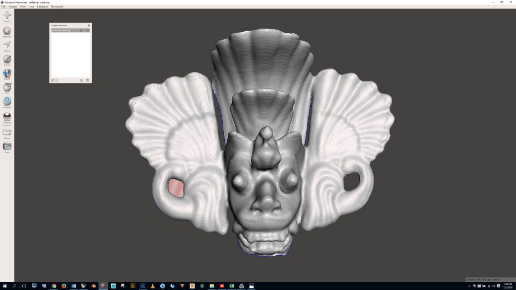
USING MESHMIXER TO CLEANUP THE MODEL
Open Meshmixer and import your model.
Notes about getting started in Meshmixer:
- Navigate the viewport:
- To orbit: hold ALT, and left mouse button
- To pan: hold middle mouse button
- To zoom: roll middle mouse button
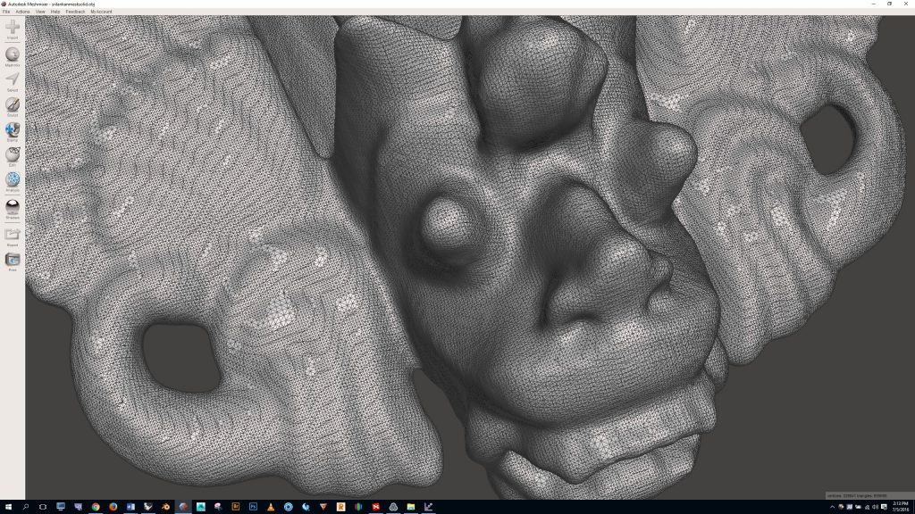
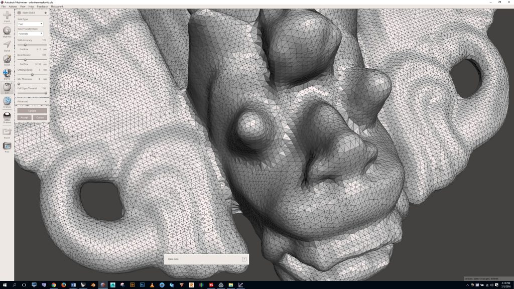
If we push the “W” key on the keyboard to turn wireframe on and we zoom in we can see that the mesh is very dense. The dense mesh will be difficult to work with, so we’ll need to simplify it. To do this, click the “edit” button on the left, then “make solid”
Meshmixer will process your scan and a dialogue box will pop up on the left. Notice that the mesh becomes quite crude. By adjusting the “solid accuracy” and “mesh density” sliders and clicking the “update” button you can make the mesh more (or less) dense. We want to find a happy medium with the complexity of the mesh so that it is dense enough to capture all the details but not so dense that it is difficult to work with.
In this case I felt that a value of 172 for solid accuracy and mesh density was optimal. To complete the make solid process, click the “accept” button.
Note: The make solid function in Meshmixer is very useful for converting bad geometry to a watertight solid. So, for example, later this semester if you download a mesh from the web that you want to work with, but you discover that there are holes or other problems with the mesh, you can use the make solid command to convert the geometry to a useable watertight format.
Next we’ll get rid of the holes in the model and smooth out the rough spots.
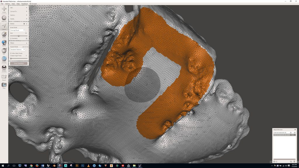
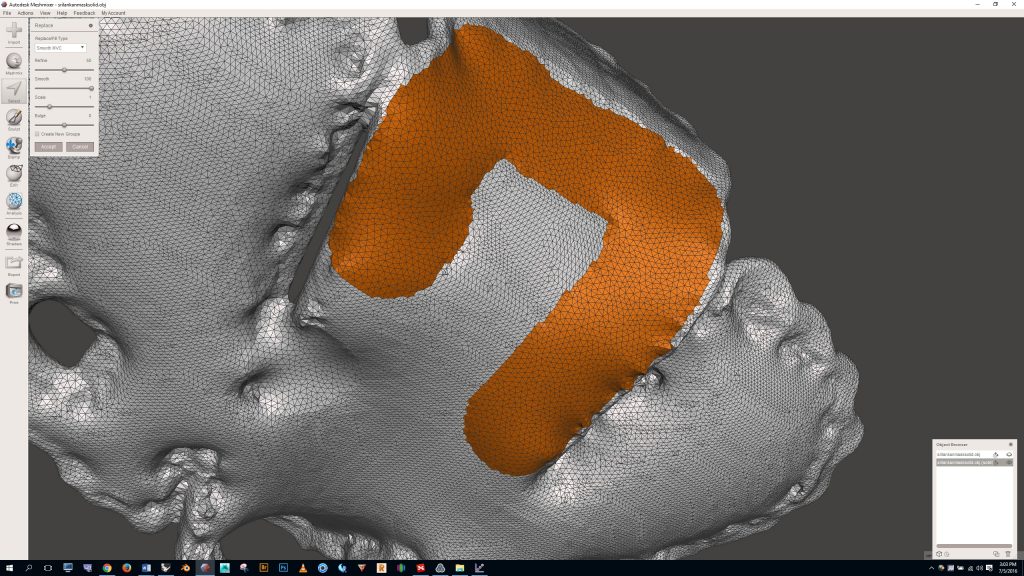
Press the “S” key to open the selection panel. Notice that by default we’re using the “unwrap brush”. Adjust the brush size by moving the slider left or right. Use the brush to select a bad portion of the model. Hold shift if you need to deselect.
Press “F” to delete and fill the problem area. If you’re satisfied with the fill you can click the accept key or simply press “S” to make your next selection.
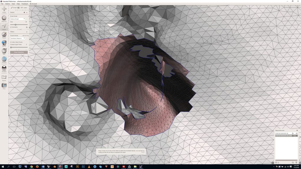
To fill deep pockets you may need to select the “sphere brush” option from the dropdown menu.
If you’re lucky in these deep areas you’ll still be able to fill by simply pressing the “f” key, as shown below.
But if you’re not so lucky you’ll get an error that looks like this. This happens because you aren’t able to grab all of the faces needed to generate good watertight geometry.
If this happens you’ll need to press “delete” to eliminate the selected faces, and then go back in to manually delete what’s left.
By default your selection brush only grabs the fronts of faces. By clicking the “allow back faces” box we can select the hard to reach faces in this cavity. When using this option be careful because it’s easy to accidentally make holes in the other side of your model.
Once all of the inner faces are deleted, select the border of the hole and press “f”
And presto! You have a filled in hole.
This method of selecting faces and pressing “f” can also be used to smooth out rough patches in the geometry, as shown below.
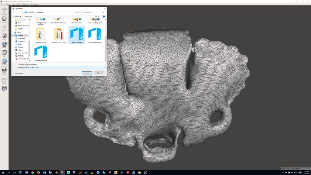
After you’ve finished filling in all of the holes and smoothing out the model, click the “export” button and save the model in OBJ format.
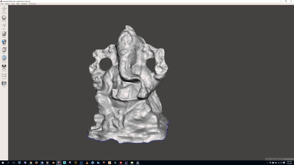
The Ganesha sculpture imported to Meshmixer as shown below:
There weren’t any big holes or rough patches to fix, so I simply needed to close the bottom of the model. I did this by clicking the “edit” button on the left and selecting “make solid”
Finally, I clicked the “export” button and saved the file as an OBJ.
