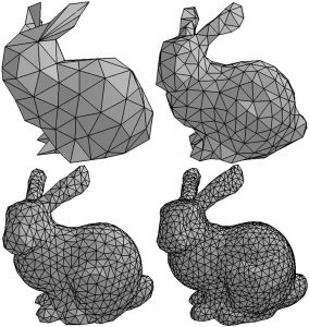
In Rhino we model with NURBS, which is a mathematical representation of form. 3D printing programs, on the other hand, work with STL and/or OBJ files, which are both mesh formats. We therefore need to convert the NURBS form to a mesh in preparation for 3D printing. It’s possible to directly export a NURBS form from Rhino as an OBJ or STL, but if you do this you won’t have a chance to inspect the mesh. It’s important to inspect the mesh because it may not capture sufficient detail, or it may be more dense than necessary. If your mesh lacks sufficient density you’ll get a faceted looking 3D print, and if the mesh is too dense you may crash the 3D printing program. With this in mind, it’s best to convert your NURBS form to a mesh, inspect it carefully, and then export.
Meshing a NURBS form
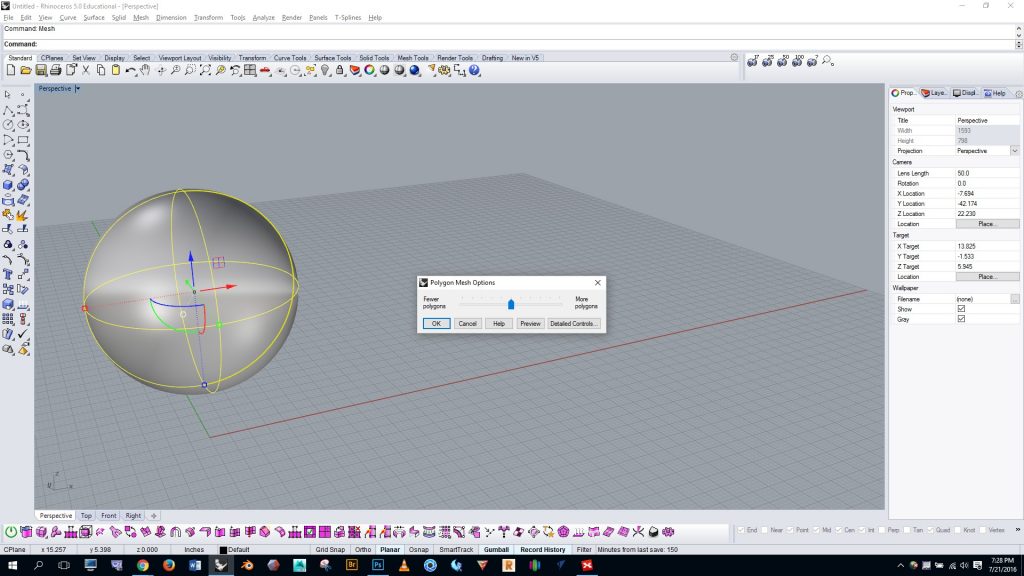
In Rhino, select your NURBS polysurface and run the “mesh” command. By default you’ll see the simple slider, as shown in the image below. For some projects you may get decent results by adjusting this single slider. However, the simple slider sometimes doesn’t give enough control. So if you click on the “detailed controls” button that’s below the slider you’ll be given more options…
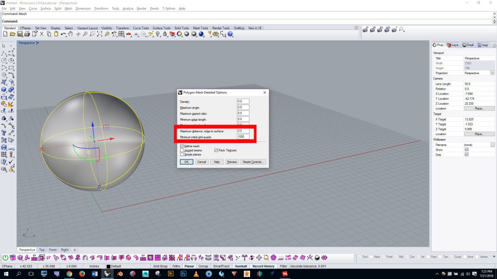
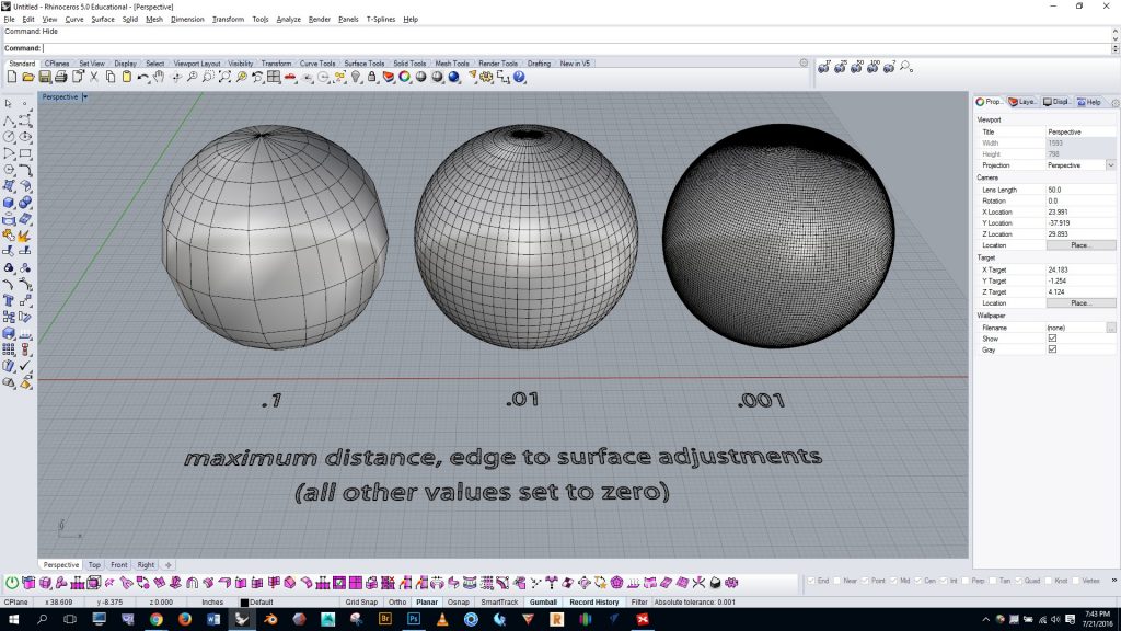
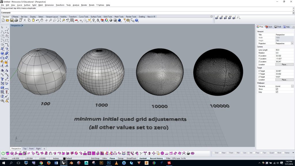
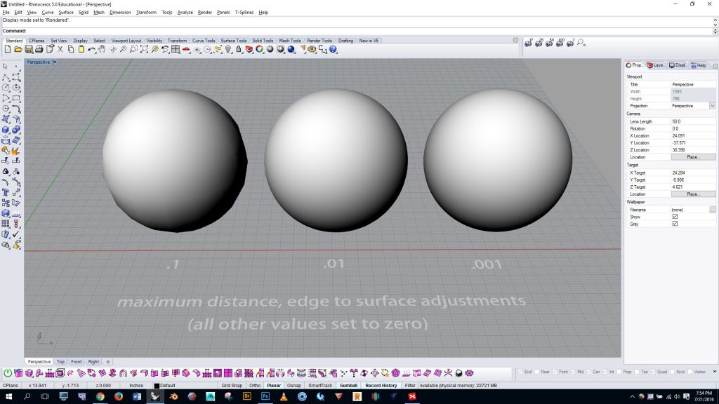
Start off by entering zero in all of the boxes, and then turn your attention to “maximum distance, edge to surface” and “minimum initial quad grids”, marked in red below. These settings have the greatest effect. You can increase the density of the mesh by lowering the value of “maximum distance, edge to surface”, or by raising the value of “minimum initial quad grids”. Some comparison meshes and settings are shown below…
Inspecting the mesh visually
You can get a good sense of the quality of the mesh by visually inspecting it. However, shaded view (as shown in the image above) and regular rendered view (as shown below) don’t enable us to accurately see what the form will look like after it is printed…
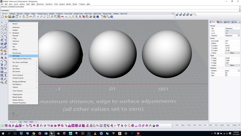
As shown below, with rendered viewing mode on, click on the dropdown arrow in the top left of the viewport, and then turn “flat shade” on.
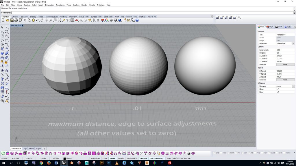
Notice in the image below how the facets on the spheres become much easier to see.
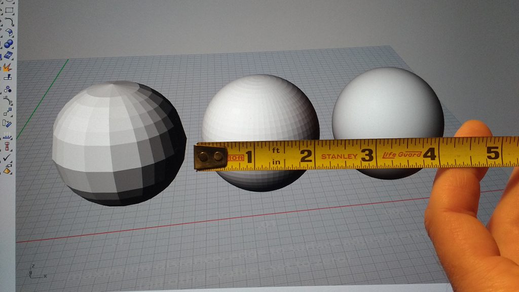
Now, to get a sense of how the mesh will look when printed we need to see the sphere at its actual scale. Get a tape measure or ruler and hold it over the monitor and then scale your object to match the size you intend for the print. In this case I’m assuming that I’ll print the sphere at 2″, and you can see that at this scale the mesh is visible. This tells me that I probably want to create a mesh of greater density than the center sphere.
Inspecting the number of verteces.
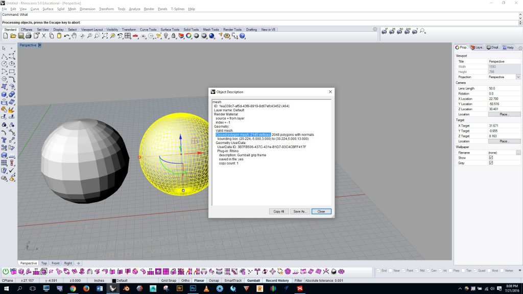
We can also inspect the mesh with the “what” command. As you can see below, the center mesh has 2,145 vertices (mesh points). This is, of course, well within the acceptable limit. However, I ran a print job in the MakerSpace the other day with a collection of parts that had 2,032,909 vertices in total, and Simplify3D ran verrrry slowly. This was probably due in part to the old processor on the MakerSpace laptop, but still, the experience gave a sense of the limitations we face. If you exceed 2,032,909 vertices you may crash the computer.
