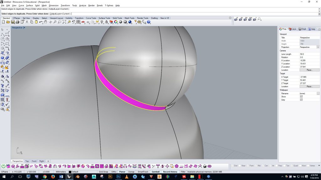
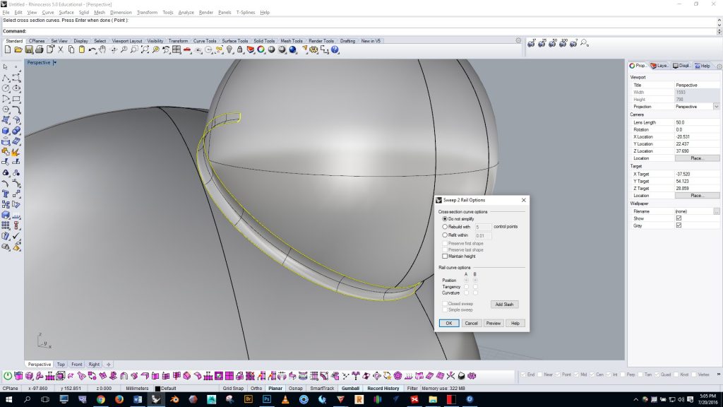
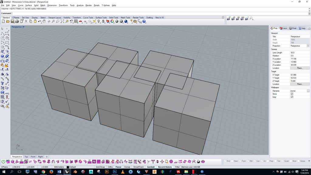
Many modifications can be done in Simplify3D and Preform, but I find it easier and faster to modify in Rhino. In Rhino we also have more control for certain operations, we have a more complete set of tools, and we’re able to use the orthographic viewports. Here are some modifications you may want to make as you prepare to 3D print your part:
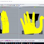
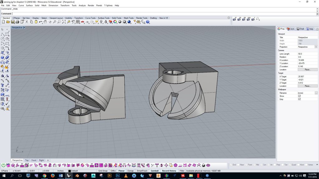
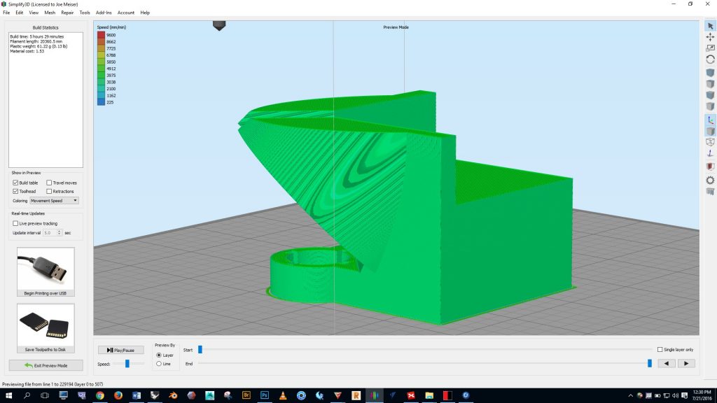
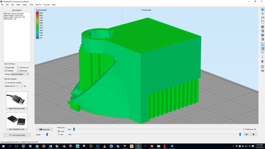
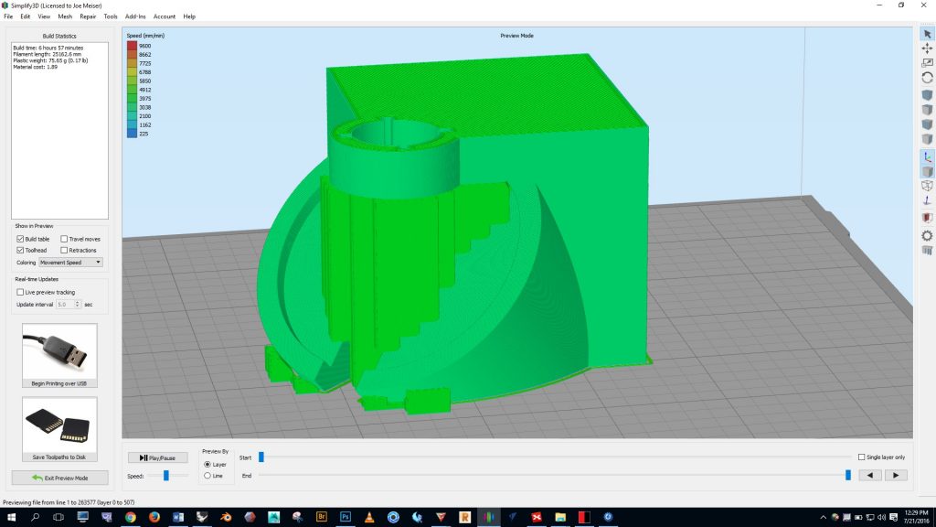
Orient parts to reduce the amount of support needed and control the placement of the support. By rotating parts in XYZ we can reduce the amount of support needed (which will speed up the print job), and we can keep support off of detailed areas (which will make post-print cleanup easier). Take a look at the example below. Here we see the same part in two different orientations. The FDM (aka FFF) printers in the MakerSpace can print a 45 degree overhang without support, so the orientation on the left can be printed without any support. See the screenshots below from Simplify3D to see how the orientation on the left would not require support, while the option on the right would require support.
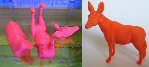
Orient parts for best resolution. Models can be sliced into pieces if necessary and then re-assembled. On Fused-Filament Fabrication printers, you can only control the Z resolution. The X and Y resolutions are determined by thread width. If your model has fine features, make sure the model orientation is cable of printing those features.
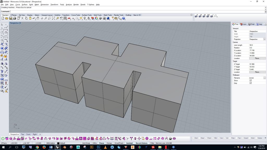
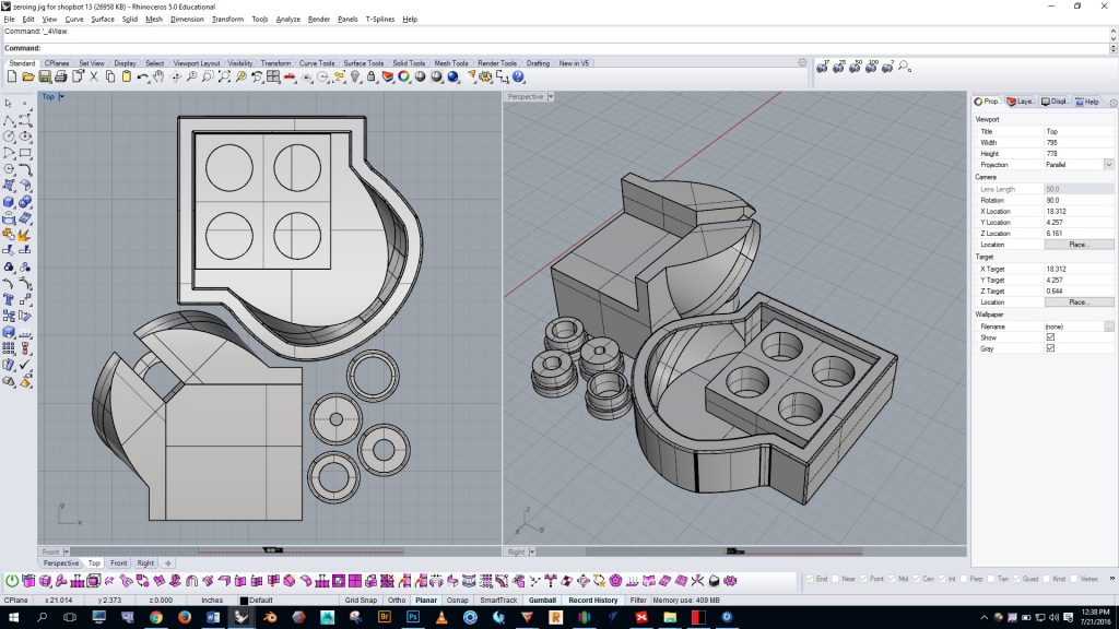
Arrange parts close together. Moving parts close together will decrease print time by reducing travel. Use the top viewport in Rhino scoot parts close together. An effective arrangement is shown below.
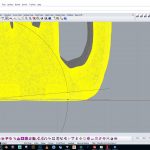
Ensure contact with ground plane. If you plan to export multiple parts from Rhino together for printing you’ll need to make sure that the bottom of each part meets the same ground plane. Use the front and side viewport to ensure that all of the parts meet the ground plane (see below). Zoom in very close to inspect.
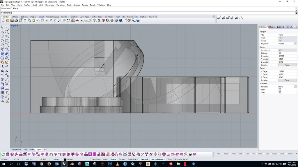
If you think a part might be too high or too low, use the move command and your osnaps to relocate it. Below you can see an example of moving the highlighted part from its bottom left corner to the bottom quadrant of one of the cylinders. Once this action is complete we can be certain that the two parts are aligned with the same ground plane.
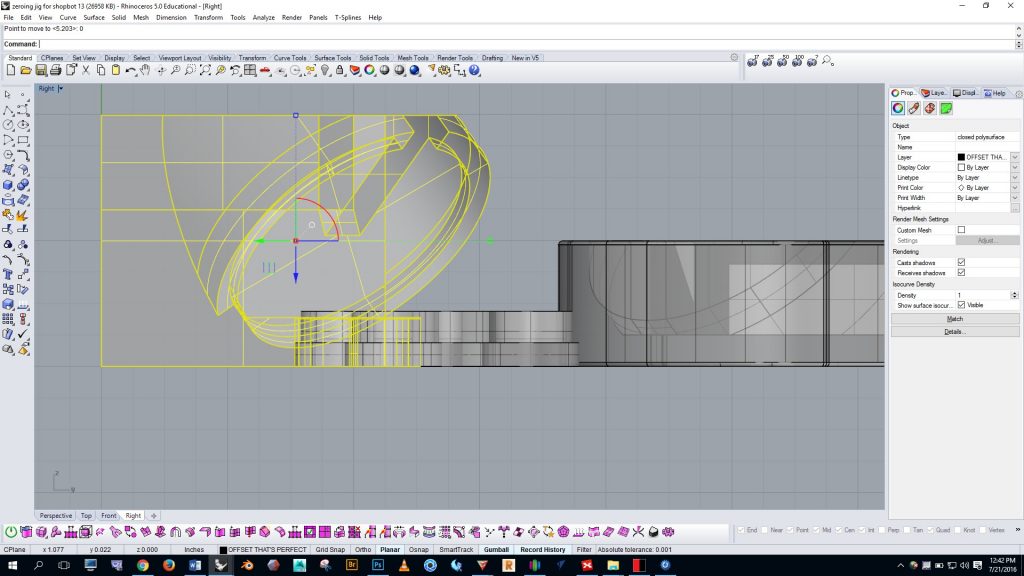

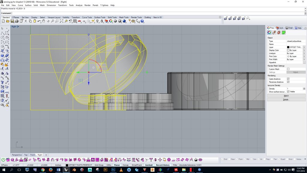
In the example below the highlighted part makes contact with the ground plane only at a single point. In this case the part needs to be rotated with the vertex osnap and ortho along both the x and y axes.
Split the model and use offset pins for registration
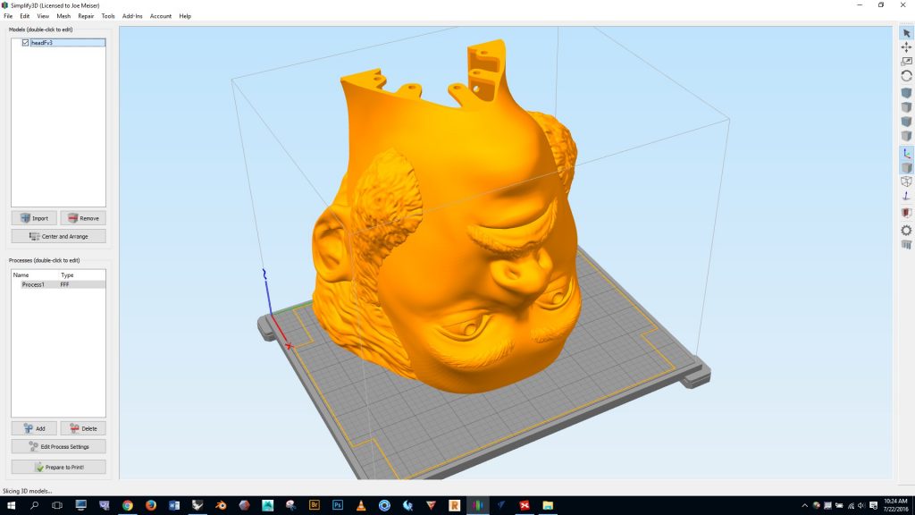
I wanted to print the project below to be 11″ tall, but the work envelope on my MakerGear printer is only 8″ x 10″ x 8″ (XYZ). I’ve drawn in the MakerGear’s work envelope in the example below.
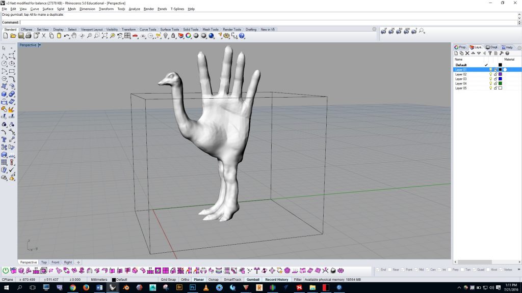
I decided to cut the form in half and print it in two parts. Obviously, this makes things a bit more difficult because then the two parts have to be assembled after it’s printed, but with registration pins the assembly becomes easier.
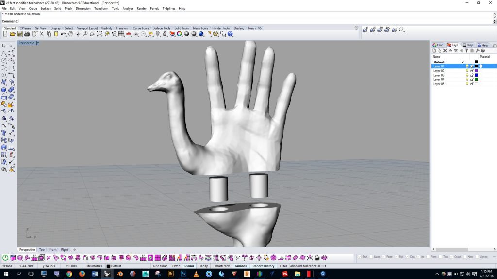
If the pins are exactly the same size as the hole they won’t fit in, so we need to make the pins slightly smaller as shown in the image below.
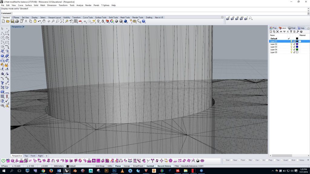
Getting the tolerances correct for interlocking parts can be difficult. Some tips: use a 0.2mm offset for a tight fit and a 0.4mm offset for loose fit {{ that is .0079″ and .016″ respectively }}. You will have to test it yourself with your particular model and the printer you’re using to determine what is the right tolerance for your situation. I found that a .4mm offset worked well for the ostrich hand pins.
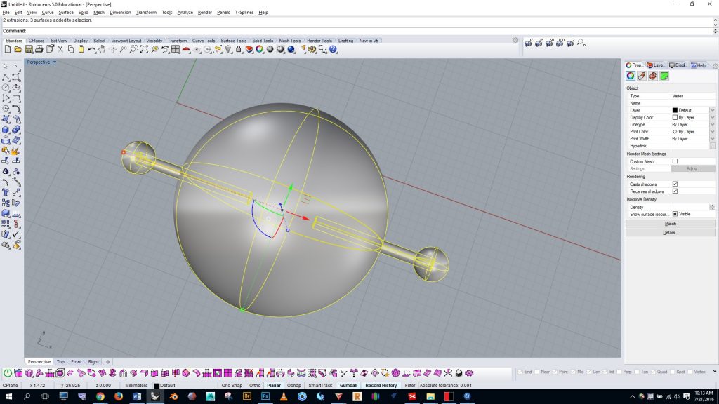
The example below shows the process of creating the holes and offset pins. We begin by creating two boxes…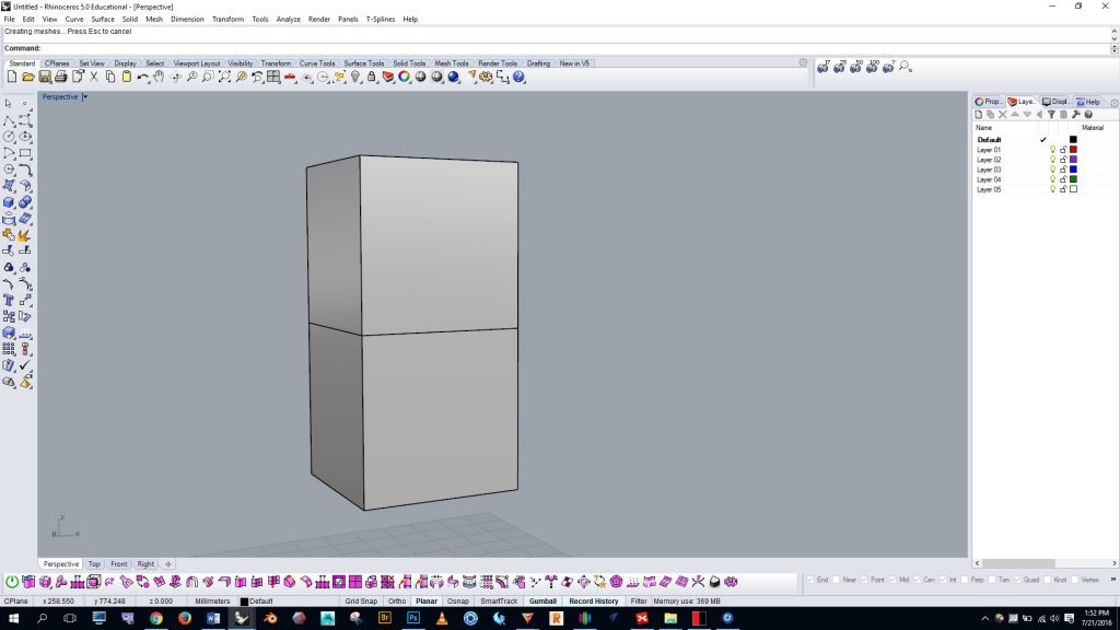
We create a cylinder in the center…
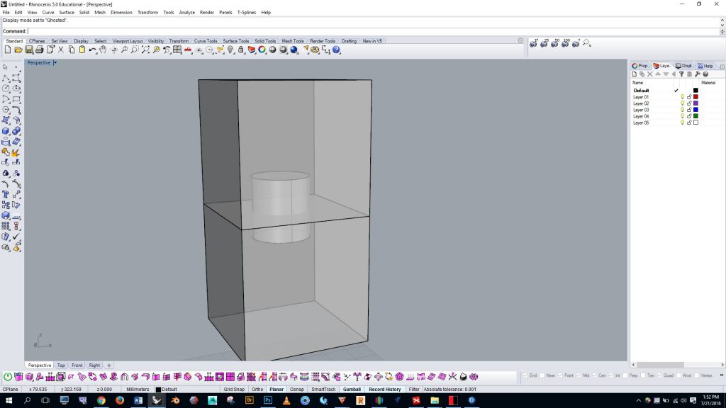
We select the cylinder and run the “offsetsrf” command, and choose to offset by .4mm…
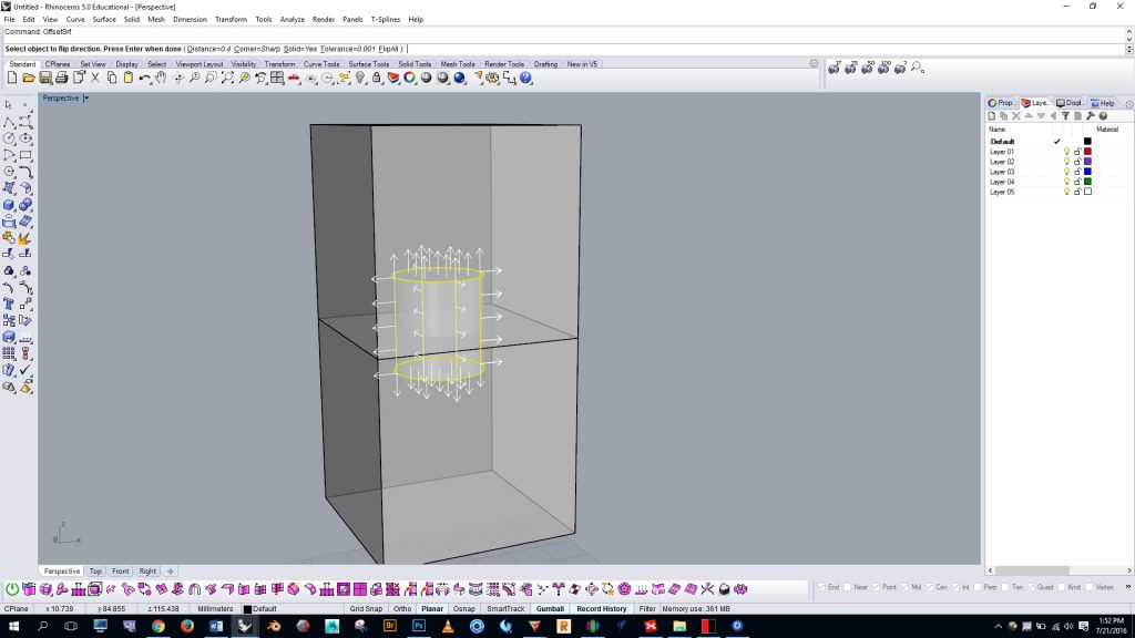
We select the outer cylinder and copy and paste it, and then hide the duplicate and the top box…
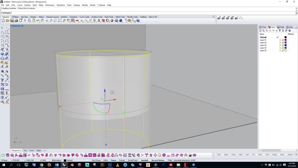
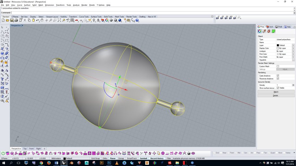
We then run the boolean difference command and delete the outer cylinder from the box…
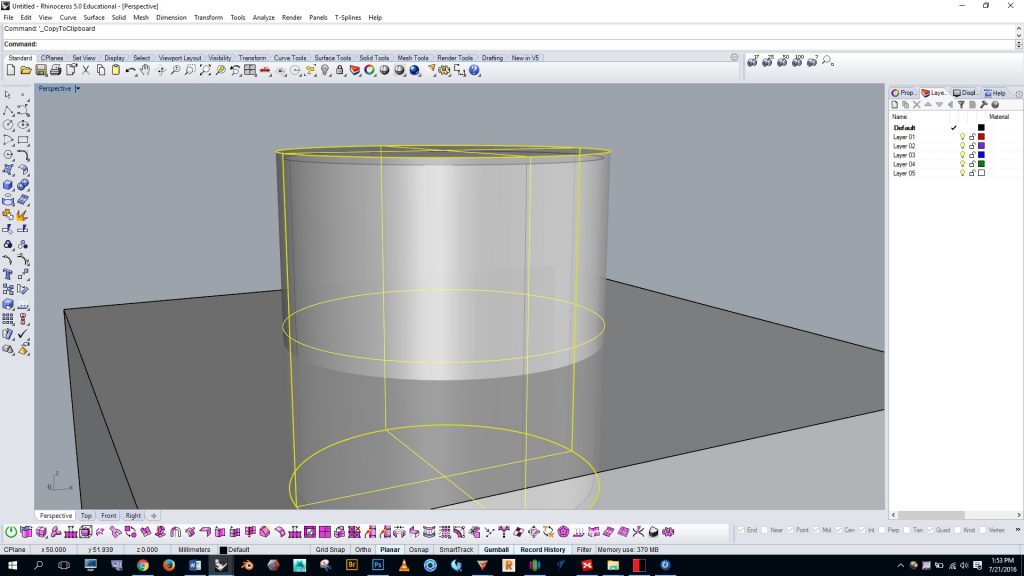
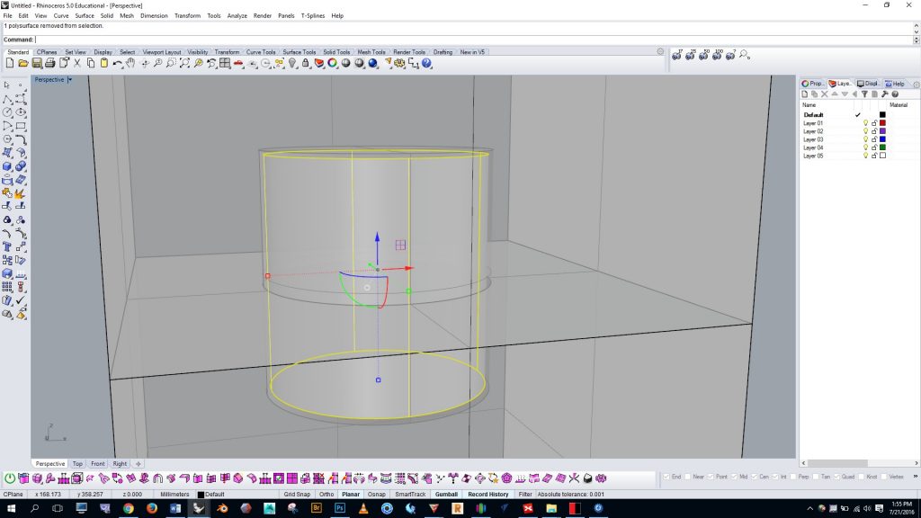
Then we show the upper box and duplicate outer cylinder and run the boolean difference command on the upper box. Finally, we have a pin and two offset holes.
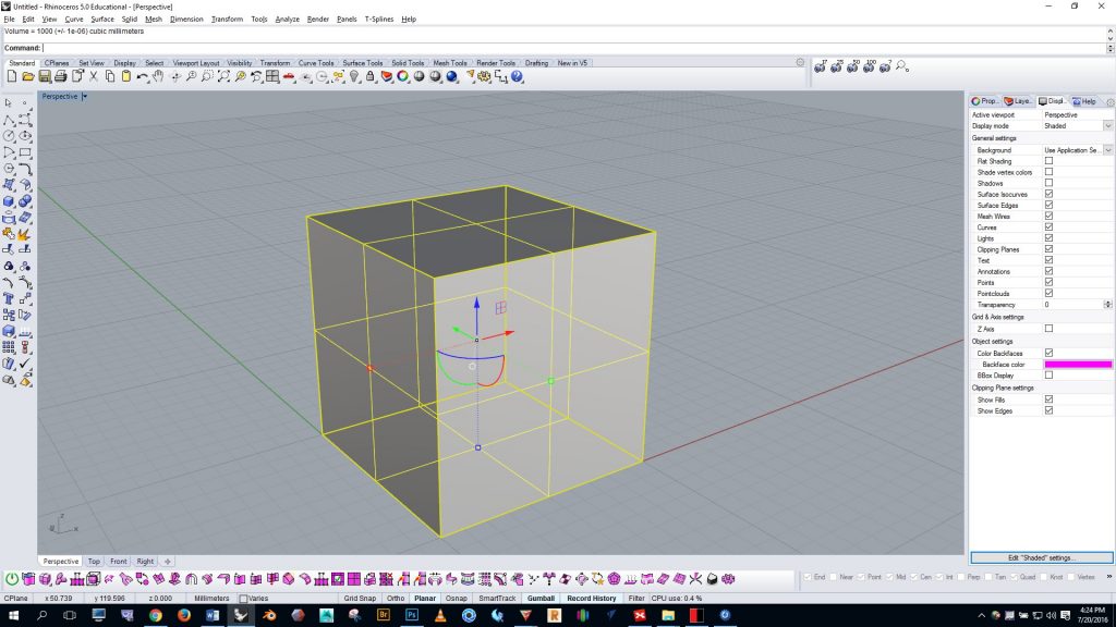
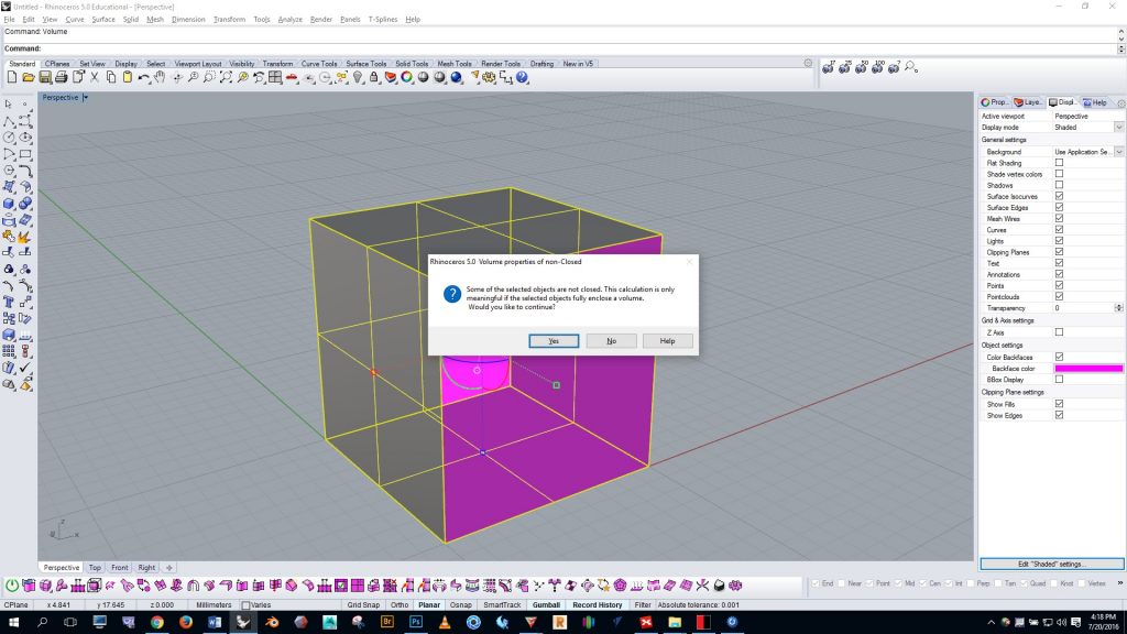
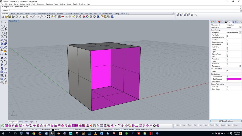
Making parts hollow in Rhino: why and how. In some situations you may want to make your project hollow to save material, lower the cost of printing, and/or reduce the weight of the print. Keep in mind that our FDM printers at the MakerSpace may have some difficulty with extremely thin walls. I generally keep my walls at least 4mm thick. Thinner walls can be achieved, but you may run into difficulty with them — especially if your project is large.
In the video below, Kyle Houchens tells why you may want to print hollow and shows how to create a hollow model.
Making parts hollow in MeshMixer. Getting a good offset interior surface can sometimes be difficult in Rhino. Sometimes it’s easier to make the part hollow in MeshMixer. To do this, first scale your model to the desired size in Rhino. Then open MeshMixer and import your part.
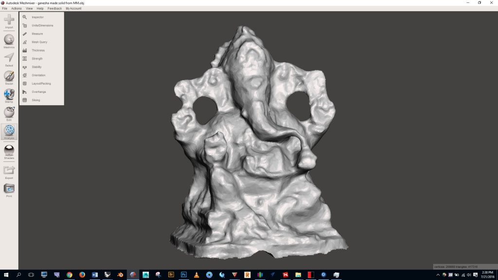
Click “edit”, select “hollow”, select the offset distance, etc.
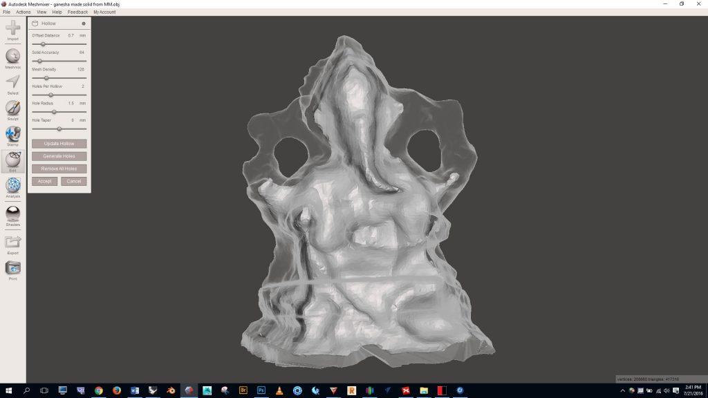
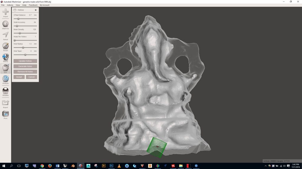
I suggest creating at least one hole in an inconspicuous spot. Without a hole you’ll have a closed form inside of another closed form, which can confuse the 3D printing program. The hole will help avoid any confusion. Notice in the image below the single green hole that will be created in the bottom. Once you’re happy with the settings click “accept” and you’ll have a hollow form. If you wanted to make further modifications to the form you could take it back into Rhino and edit it with mesh boolean processes.
[return to 3D Printing Guide main page]
[return to top]
